PCB: Difference between revisions
(→Wheel) |
|||
| (6 intermediate revisions by the same user not shown) | |||
| Line 17: | Line 17: | ||
====Steering==== | ====Steering==== | ||
* 1: 12V, | * 1: 12V, | ||
* 2: PWM pin 5 - moved to pin 29 (timer FTM2 200 Hz?), | * 2: PWM pin 5 - moved to pin 29 (timer FTM2 200 Hz?), Patch on rev A2, clean in rev B | ||
* 3:pot pin 23 (A9), | * 3:pot pin 23 (A9), | ||
* 4: GND | * 4: GND | ||
| Line 30: | Line 30: | ||
* 1: 5V | * 1: 5V | ||
* 2: A pin 39 | * 2: A pin 39 | ||
* 3: B pin 30 - patched from A21 DAC0 | * 3: B pin 30 - patched from A21 DAC0 on rev A2, clean on rev B | ||
* 4: GND | * 4: GND | ||
current sensor | current sensor | ||
| Line 44: | Line 44: | ||
encoder | encoder | ||
* 1: 5V | * 1: 5V | ||
* 2: A pin 5 - patched from A22/DAC1 | * 2: A pin 5 - patched from A22/DAC1 on rev A2, clean on rev B | ||
* 3: B pin 36 | * 3: B pin 36 | ||
* 4: GND | * 4: GND | ||
| Line 51: | Line 51: | ||
* 2: sense pin 15 (A1) | * 2: sense pin 15 (A1) | ||
* 3: gnd | * 3: gnd | ||
====Wheel==== | ====Wheel==== | ||
motor driver | motor driver | ||
* 1: nc (not connected on rev | * 1: nc (not connected on rev B, must not be connected on rev A2 (+5V source both ends)) | ||
* 2: PWM pin 2 (timer FTM3) (S1) (RC mode 200 Hz?) | * 2: PWM pin 2 (timer FTM3) (S1) (RC mode 200 Hz?) | ||
* 3: GND - NB! connected to motor power GND (probably OK to connect) | * 3: GND - NB! connected to motor power GND (probably OK to connect) | ||
| Line 86: | Line 87: | ||
[[File:leg_teensy_board.png | 600px]] | [[File:leg_teensy_board.png | 600px]] | ||
Figure 4. Layout of PCB (designed in Eagle). | Figure 4. Layout of PCB revision A2 (designed in Eagle). | ||
| Line 92: | Line 93: | ||
[[File:leg_teensy_schematic.png | 500px]] | [[File:leg_teensy_schematic.png | 500px]] | ||
Figure 5. PCB schematic - click on image to get better view. | Figure 5. PCB schematic revision A2 - click on image to get better view. | ||
[[File:teensy_board_patches_annotated.png | 500px]] | [[File:teensy_board_patches_annotated.png | 500px]] | ||
Figure 6. Needed patches from version A2 to | Figure 6. Needed patches from version A2 to revision B. PWM for steering servo in RC mode now moved to timer FMT3 on pin 29 (old connection to pin 5 must be cut). Actuator 2 encoder A also connected to pin 5 (for interrupt), and actuator 1 encoder B also connected to (free) pin 30 - also for interrupt (annotated image has error Act 1<->2). The last 2 maintains connection to DAC pins and pull-up resistors. | ||
---- | ---- | ||
--[[User:Jca|Jca]] ([[User talk:Jca|talk]]) 13:03, 9 June 2018 (CEST) | --[[User:Jca|Jca]] ([[User talk:Jca|talk]]) 13:03, 9 June 2018 (CEST) | ||
Latest revision as of 17:28, 27 October 2018
Back to Flexbot main page
Flexbot PCBs
Teensy board
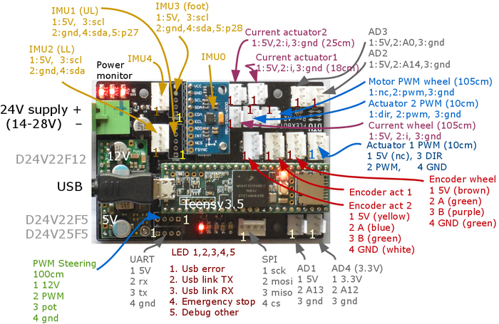
Figure 1. Plug names and pin allocation for Teensy board.
- IMU0, on-board, SCL0, pin 18-19, AD0=NC, Knee.
- IMU1, SCL1, pin 37_38, AD0=HIGH (pin 27), Thigh (upper leg).
- IMU2, SCL1, pin 37_38, AD0=NC, Shin (lower leg).
- IMU3, SCL2, pin 3_4, AD0 = HIGH (pin 28), Foot.
- IMU4, SCL2, pin 3_4, AD0 = NC, Hip.
Actuators
Steering
- 1: 12V,
- 2: PWM pin 5 - moved to pin 29 (timer FTM2 200 Hz?), Patch on rev A2, clean in rev B
- 3:pot pin 23 (A9),
- 4: GND
Actuator 1 - upper leg
motor
- 1: (5V) nc.
- 2: PWM pin 21 (timer FMT3)
- 3: direction pin 26
- 4: GND
encoder
- 1: 5V
- 2: A pin 39
- 3: B pin 30 - patched from A21 DAC0 on rev A2, clean on rev B
- 4: GND
current sensor
- 1: 5V
- 2: sense pin 16 (A2)
- 3: gnd
Actuator 2 - lower leg
Motor
- 1: direction pin 25
- 2: PWM pin 22 (timer FMT0)
- 3: GND
encoder
- 1: 5V
- 2: A pin 5 - patched from A22/DAC1 on rev A2, clean on rev B
- 3: B pin 36
- 4: GND
current sensor
- 1: 5V
- 2: sense pin 15 (A1)
- 3: gnd
Wheel
motor driver
- 1: nc (not connected on rev B, must not be connected on rev A2 (+5V source both ends))
- 2: PWM pin 2 (timer FTM3) (S1) (RC mode 200 Hz?)
- 3: GND - NB! connected to motor power GND (probably OK to connect)
encoder
- 1: 5V
- 2: A pin 35
- 3: B pin 34
- 4: GND
current
- 1: 5V
- 2: sense pin 17 (A3)
- 3: GND
Cables in leg
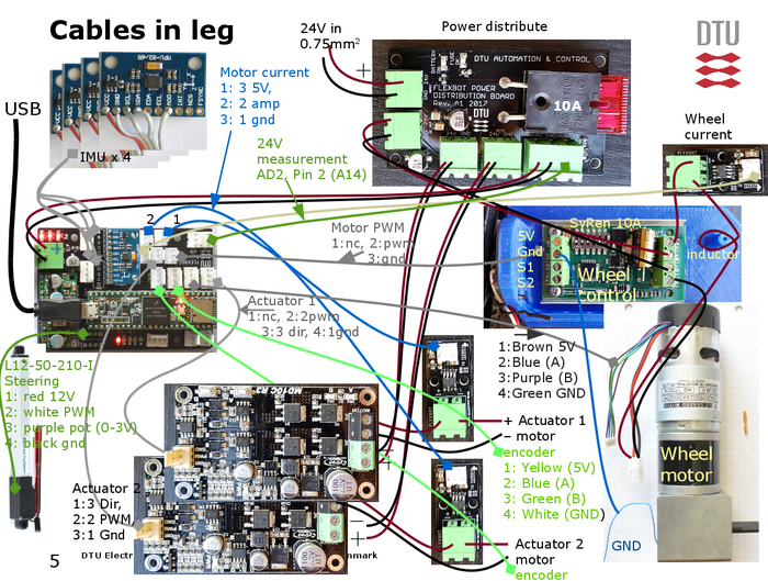
Figure 2. Overview of cables in one leg with some wire details. The connection to robot base platform is 24V (10A) and USB only. Steering servo should be in RC servo interface mode.
Wheel motor driver in RC mode: switch 1=off, all others ON. S1 used only.
Controller block diagram
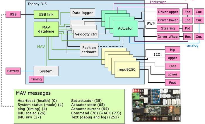
Figure 3. Functional blockdiagram og Teensy controller board. Not all blocks and MAV messages are implemented yet.
Teensy board and schematic
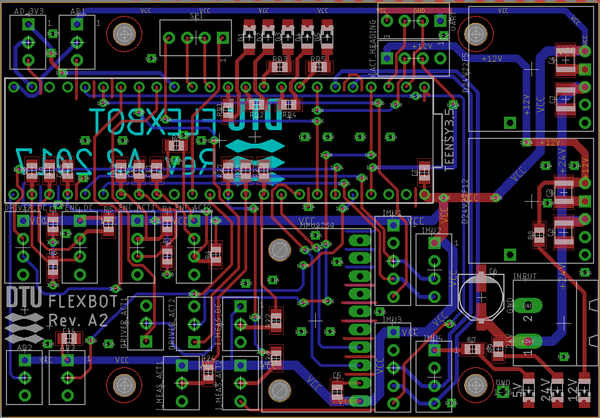
Figure 4. Layout of PCB revision A2 (designed in Eagle).
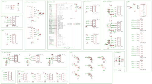
Figure 5. PCB schematic revision A2 - click on image to get better view.
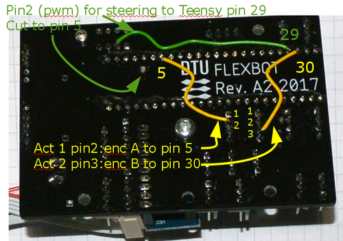
Figure 6. Needed patches from version A2 to revision B. PWM for steering servo in RC mode now moved to timer FMT3 on pin 29 (old connection to pin 5 must be cut). Actuator 2 encoder A also connected to pin 5 (for interrupt), and actuator 1 encoder B also connected to (free) pin 30 - also for interrupt (annotated image has error Act 1<->2). The last 2 maintains connection to DAC pins and pull-up resistors.
