ASTA motion capture: Difference between revisions
| (One intermediate revision by the same user not shown) | |||
| Line 4: | Line 4: | ||
== More data == | == More data == | ||
=== Optitrack | === Optitrack Motive link === | ||
https://optitrack.com/software/motive/ | |||
=== Raspberry PI === | === Raspberry PI === | ||
| Line 184: | Line 184: | ||
2. Download the [https://optitrack.com/software/natnet-sdk/ NatNet SDK] and check out the examples. | 2. Download the [https://optitrack.com/software/natnet-sdk/ NatNet SDK] and check out the examples. | ||
This is ported to Raspberry PI at [[Raspberry | This is ported to Raspberry PI at [[Optitrack on Raspberry Pi]] | ||
== Archive (in case the system needs to be reassembled) == | == Archive (in case the system needs to be reassembled) == | ||
Latest revision as of 11:20, 3 October 2024
Back to ASTA
More data
Optitrack Motive link
https://optitrack.com/software/motive/
Raspberry PI
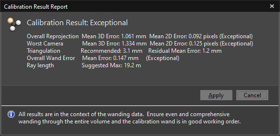
Calibration test
Specs
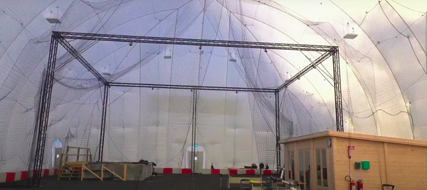
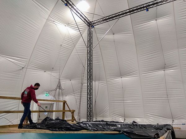
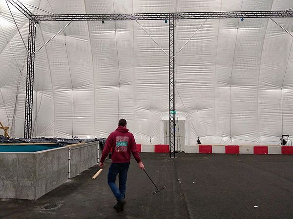
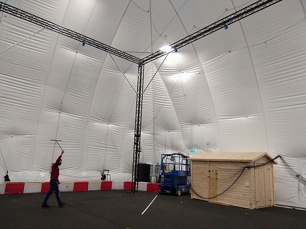
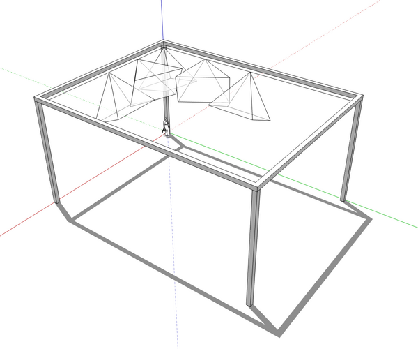
- Covered area: 16 m x 12 m and camera height 8 m
- Accuracy: < 5 mm
- Repetability: < 1 mm
- Number of cameras: 16
- Camera type: Prime 17W
Start up
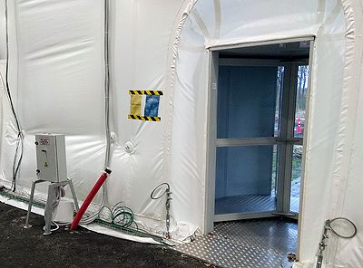
- Depending on the lighting conditions, switch on the reflectors. The switch stands on the right-hand side after entering through the rotating door.
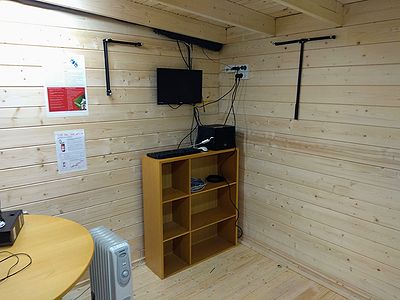
- Find the motion capture computer in the central shed, and turn it on by pressing on the "cooling master" logo.
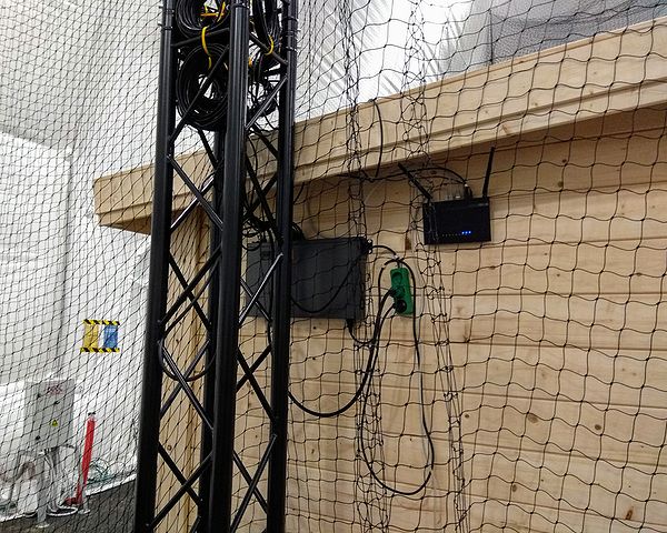
- Make sure the cameras are on - i.e. the black network switch on the wall outside the shed (combining all the camera cables).
Calibration
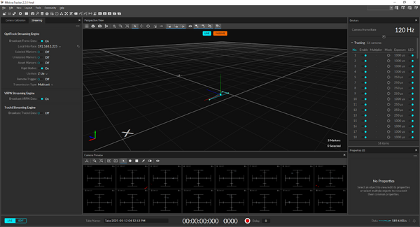
1. Start Motive.
Motive is loading the last calibration and rigid bodies last used, and maybe the calibration is sufficient already.
The camera truss is hopefully sufficiently stable so that you don't need daily calibration.
If your rigid body shows additional reflectors and/or the position of the rigid body flickers too much, then one or more cameras are not sufficiently calibrated.
- Existing calibrations can be loaded using 'File->open' - e.g. with a different origin or volume accuracy.
New calibration
2. Make sure that no reflectors (or reflecting surfaces) are present in the capture volume.
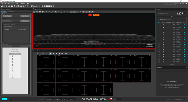
3. Find the calibration pane on the left-hand side
4. Press "Clear Mask"
5. Press "Mask Visible"
6. Press "Start Wanding"
When motive is starting, it sometime uses only half of the cameras for calibration.
The messagebox should say "16 of 16 cameras selected for calibration", but then if the number of cameras listed under "Wanding" doesn't total to 16 (the numbering doesn't matter), restart Motive and repeat steps 3-6.
If the messagebox say e.g. "1 of 16 cameras selected for calibration", then select all cameras by holding down 'shift' and click all cameras and try again.
7. Find the calibration wand hanging on the right-hand side of the computer.
8. Walk the wand through the capture volume at a speed of 1 m/s. Draw a circle right above the surface of the pool.
9. Draw another circle right above the ground on the remaining area.
10. Draw a third circle higher up.
11. Walk back to the central shed, hang the wand where it was, come back to the motion capture computer, and press "Calculate". The result should be at least "Great", and ideally, "Exceptional".
12. If it is the case, press "Apply". Otherwise, repeat steps 6-11.
If the calibration keeps being insufficient, restart Motive and repeat steps 3-11
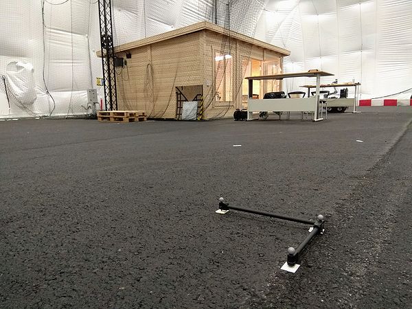
13. Fing the L-shaped calibration square on the left-hand side of the computer, and lay it at the center of the capture volume using the white pieces of tapes as guides.
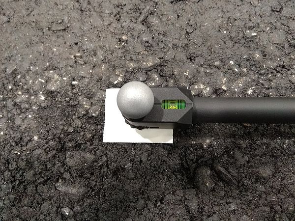
14. Make sure that the calibration square is leveled by looking at the bubble levels. If it's not the case, adjust the height of the legs.
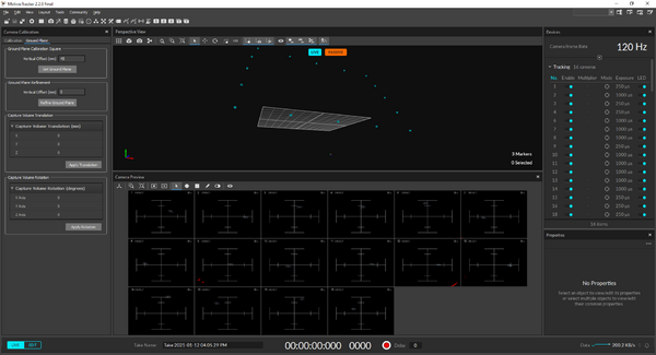
15. Come back to the motion capture computer, find the "Ground Plane" tab in the "Calibration" pane, and press "Set Ground Pane".
- The X-axis (red) is pointing North and the Z-axis (blue) is pointing East (Y (green) is up).
- (The cameras are at the North end of the dome).
Adding an asset
1. Attach at least 4 markers to the robot (the more, the better) while avoiding symmetries.
2. Place the robot next to the origin with its body axis parallel to the fixed axis.
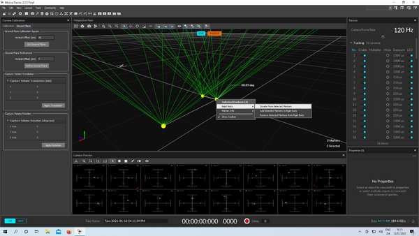
3. In Motive, select all the markers associated with the robot, right-click, and select "Rigid Body" > "Create From Selected Markers".
Streaming data
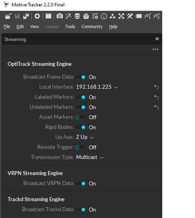
1. Find the "Streaming" pane and enable "VRPN" for use with ROS clients and "Optitrack" for use with "NatNet" (windows only) clients.
That will enable streaming on the following two networks: asta_optitrack and asta_optitrack_5G (using the 5GHz band).
Please contact [davwu@dtu.dk] for authentication information and administration.
WARNING: If a remote controller uses the same frequency as the wifi network, there might be collisions. Make sure to use the 5GHz wifi if a remote operates on 2.4 GHz and vice-versa.
Using ROS clients
2. In Ubuntu 18.04 (ROS Melodic) or Ubuntu 20.04 (ROS Noetic), fire up a terminal and install ASTA's ROS workspace collection:
git clone https://github.com/DavidWuthier/asta_workspace_setup.git
cd asta_workspace_setup
sudo chmod +x asta_workspace_setup.sh
./asta_workspace_setup.sh
3. Chain your current workspace to the VRPN workspace:
cd /path/to/your/current/workspace
catkin config --extend ~/asta_ws/vrpn_ws/devel
catkin clean -y
catkin build
4. Launch the client with the server address that can be found under "Local Interface" in the "Streaming" pane:
roslaunch vrpn_client_ros sample.launch server:=192.168.1.225
Using NatNet clients (C++ on Ubuntu or C/C++/C#/VB/.Net/Matlab on Windows)
2. Download the NatNet SDK and check out the examples.
This is ported to Raspberry PI at Optitrack on Raspberry Pi
Archive (in case the system needs to be reassembled)
Mount cameras on joints and joints on clamps
Make sure that the camera is not upside-down.
Prepare 16 safety ropes to prevent accidental camera drops
- Cut 1 m length of 8 mm nylon rope
- Use a lighter at both ends
- prepare 8-knots as in rock climbing
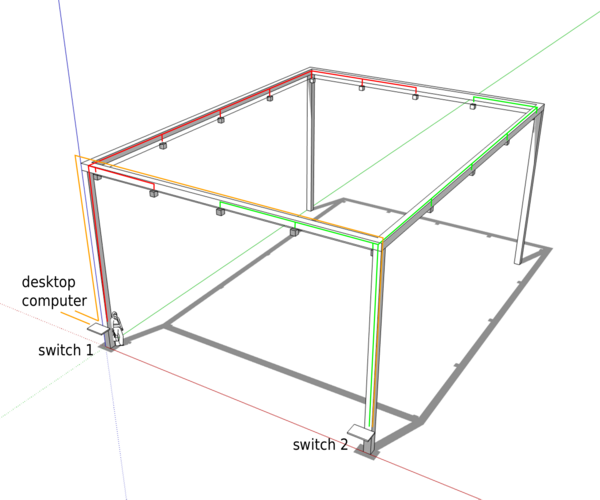
Mount cameras on truss and wire them with the two switches
Mount the 16 cameras in the corners and at each 1/4 of the edges. Use the safety ropes, and wire them to the two switches as below.
Orient cameras and adjust focus
Once the setup is up-and-running, adjust the focus of each camera using a marker at 2/3 of the working distance. Use a remote desktop app and ethernet connection.
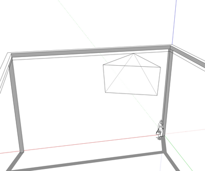
- In the corners: the bottom of FoV is parallel to the long edges, and the bottom right corner is vertical.
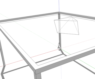
- At 1/4 of a short: the top of the FOV is horizontal, and the camera points toward the center.
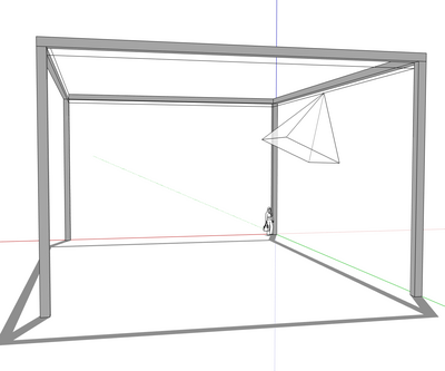
- At 1/2 of a short edge: the bottom of the FOV is vertical, and the camera aims downward.
- At 1/4 of a long edge: the top of the FOV is horizontal, and the camera points toward the center.
- At 1/2 of a long edge: the bottom of the FOV is vertical, and the camera aims downward.
