To do: Difference between revisions
From Rsewiki
(→Foot) |
|||
| (21 intermediate revisions by 2 users not shown) | |||
| Line 1: | Line 1: | ||
Flexbot design to do list | |||
Possible improvements, design ideas and other suggestions. | |||
Back to [[Flexbot]] main page | |||
=Mechanics= | |||
[[Flexbot 3D print]] status | |||
==== Motor and turn part==== | == Foot == | ||
* Turn (king-pin) bolt should be 5mm, and with bigger cone for the screw. | Assembly order: | ||
* Cut-out for motor, for raised ring on motor, should be bigger. | * Fix connection (motor-to-axle-mount) to wheel axle with 2x4mm short screws, before inserting into alu wheel-stear-mount | ||
* Alu wheel-steer-mount (with 4 bearings), insert axle assembly (from above) and secure it with wheel-nut - and fasten with pinol | |||
* Insert 5-6mm cylinder peace into turn bearings in wheel-steer-mount, and mount into steer-mount (non turning part) with 2x5mm screws and self-locking nuts. Make sure turn motion is OK. | |||
* Assemble motor and motor-mount block with 4x3mm screws into motor - make sure that motor in upright orientation and motor-mount matches wheel-steer-mount orientation. | |||
* Insert motor and motor-mount assembly into axle and fixate it to wheel-steer-mount with 2x3mm 50mm long screws and self locking nuts. | |||
* Tighten motor axle into aluminum flex motor-to-axle and fix it in one end at a time - as possible. Try turn motor or wheel to verify smooth turning. | |||
* Mount foot-base (big block) to steer-mount with 4x long self cutting screws | |||
* for steering mount blocks on motor (with strip) and on foot-base (4xsmall self cutting screws) | |||
* Mount Firgelli actuator for steering actuation with 2x 4mm 25-35mm long screws and self locking nuts. | |||
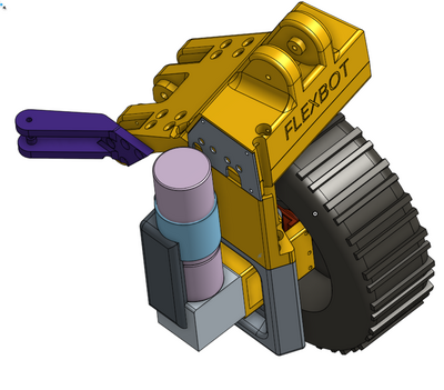
[[File:foot+motor.png|400px]] | |||
Front right wheel and foot part. | |||
====Motor and turn part==== | |||
(first number is priority, 1. is must, 2. is can maybe do without, 3. would be nice) | |||
* 2. Turn (king-pin) bolt should be 5mm, and with bigger cone for the screw. | |||
* 3. Cut-out for motor (on face with motor axle), for raised ring on motor, should be bigger in diameter. | |||
====Big block==== | ====Big block==== | ||
* | * 2. Make hole for motor driver cooling. | ||
* | * 2. use higher temperature for orange PETG plastic print (165 degree, not 162) | ||
* | |||
* | ====Steering==== | ||
* | * 1. Mount block on foot do not allow full actuator movement | ||
* 2. Mount of Firgelli too sloppy, maybe a plastic adaptor in each end? | |||
* 1. Mount block in foot end has too small screws, and may be too week. | |||
==Knee== | |||
==Hip== | |||
==Main body== | |||
=Electronics= | |||
==Power== | |||
* Main power 6-cell LiPo nominel 22.2V (between 20V and 28.5V) | |||
==Teensy== | |||
* Teensy 3.2 and Teensy 3.5 for (first level) real time control loops | |||
==Main PC== | |||
* Look at a Intel Nuc | |||
==Sensors== | |||
=Matlab Model= | |||
= | =Software= | ||
== | ==Communication== | ||
* Losing IMU i2c communication at knee | |||
== | ==Control== | ||
Latest revision as of 14:56, 8 June 2018
Flexbot design to do list
Possible improvements, design ideas and other suggestions.
Back to Flexbot main page
Mechanics
Flexbot 3D print status
Foot
Assembly order:
- Fix connection (motor-to-axle-mount) to wheel axle with 2x4mm short screws, before inserting into alu wheel-stear-mount
- Alu wheel-steer-mount (with 4 bearings), insert axle assembly (from above) and secure it with wheel-nut - and fasten with pinol
- Insert 5-6mm cylinder peace into turn bearings in wheel-steer-mount, and mount into steer-mount (non turning part) with 2x5mm screws and self-locking nuts. Make sure turn motion is OK.
- Assemble motor and motor-mount block with 4x3mm screws into motor - make sure that motor in upright orientation and motor-mount matches wheel-steer-mount orientation.
- Insert motor and motor-mount assembly into axle and fixate it to wheel-steer-mount with 2x3mm 50mm long screws and self locking nuts.
- Tighten motor axle into aluminum flex motor-to-axle and fix it in one end at a time - as possible. Try turn motor or wheel to verify smooth turning.
- Mount foot-base (big block) to steer-mount with 4x long self cutting screws
- for steering mount blocks on motor (with strip) and on foot-base (4xsmall self cutting screws)
- Mount Firgelli actuator for steering actuation with 2x 4mm 25-35mm long screws and self locking nuts.
Front right wheel and foot part.
Motor and turn part
(first number is priority, 1. is must, 2. is can maybe do without, 3. would be nice)
- 2. Turn (king-pin) bolt should be 5mm, and with bigger cone for the screw.
- 3. Cut-out for motor (on face with motor axle), for raised ring on motor, should be bigger in diameter.
Big block
- 2. Make hole for motor driver cooling.
- 2. use higher temperature for orange PETG plastic print (165 degree, not 162)
Steering
- 1. Mount block on foot do not allow full actuator movement
- 2. Mount of Firgelli too sloppy, maybe a plastic adaptor in each end?
- 1. Mount block in foot end has too small screws, and may be too week.
Knee
Hip
Main body
Electronics
Power
- Main power 6-cell LiPo nominel 22.2V (between 20V and 28.5V)
Teensy
- Teensy 3.2 and Teensy 3.5 for (first level) real time control loops
Main PC
- Look at a Intel Nuc
Sensors
Matlab Model
Software
Communication
- Losing IMU i2c communication at knee
