Robobot Hardware: Difference between revisions
From Rsewiki
(Created page with "The main board that controls the hardware is from Regbot") |
|||
| (16 intermediate revisions by the same user not shown) | |||
| Line 1: | Line 1: | ||
The main board that controls the hardware is from [[Regbot]] | Back to [[Robobot]] main page. | ||
== Introduction == | |||
The main board that controls the hardware is from [[Regbot version 4]], But there is additions: | |||
* A Raspberry pi 3 is the mission computer that integrates everything. | |||
* A Raspberry Pi camera (version 2.1) | |||
* line sensor rev-C | |||
* An O-LED display from Hobbyelectronics - see figure 1 below. | |||
===Line sensor=== | |||
[[File:line-sensor-annotated.png|600px]] | |||
Figure 1. New wider line sensor, but same circuit as the REGBOT version. | |||
===Oled Display=== | |||
[[File:oled-display.png|200px]] | |||
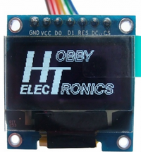
Figure 2. Oled display 128x64 pixels for Raspberry PI, showing IP address and other relevant information. | |||
Wireing: | |||
OLED Raspberry Pi | |||
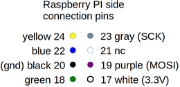
GND -------- GND (pin 20 (black)) | |||
VCC -------- 3.3V (pin 17 (white (-red))) | |||
D0 -------- D13(SCK) (pin 23 (grey)) | |||
D1 -------- D11(MOSI) (pin 19 (purple )) (MISO pin 21 not connected) | |||
RES -------- D9 (pin 22 (blue)) | |||
DC -------- D8 (pin 18 (green)) | |||
CS -------- D10 (pin 24 (yellow)) | |||
[[File:oled-wirering.png|200px]] | |||
[[File:oled-pi-side.png|260px]] | |||
[[File:oled-oled-connection.png|260px]] | |||
Figure 2. Wiring from Oled to raspberry pi - SPI connection | |||
Latest revision as of 08:45, 5 January 2019
Back to Robobot main page.
Introduction
The main board that controls the hardware is from Regbot version 4, But there is additions:
* A Raspberry pi 3 is the mission computer that integrates everything.
* A Raspberry Pi camera (version 2.1)
* line sensor rev-C
* An O-LED display from Hobbyelectronics - see figure 1 below.
Line sensor
Figure 1. New wider line sensor, but same circuit as the REGBOT version.
Oled Display
Figure 2. Oled display 128x64 pixels for Raspberry PI, showing IP address and other relevant information.
Wireing:
 OLED          Raspberry Pi
  GND -------- GND (pin 20 (black))
  VCC -------- 3.3V (pin 17 (white (-red)))
   D0 -------- D13(SCK) (pin 23 (grey))
   D1 -------- D11(MOSI) (pin 19 (purple )) (MISO pin 21 not connected)
  RES -------- D9 (pin 22 (blue))
   DC -------- D8 (pin 18 (green))
   CS -------- D10 (pin 24 (yellow))
Figure 2. Wiring from Oled to raspberry pi - SPI connection


