Drone firmware: Difference between revisions
No edit summary |
|||
| (11 intermediate revisions by the same user not shown) | |||
| Line 3: | Line 3: | ||
== Functional overview == | == Functional overview == | ||
[[File:data-flow-block.png | | [[File:data-flow-block.png | 850px]] | ||
Figure. Overall data flow for drone flight | Figure. Overall data flow for the drone flight controller. Most blocks also refer to tabs in the GUI (drone_gui). | ||
[[File:block-functions.png | 500px]] | [[File:block-functions.png | 500px]] | ||
| Line 11: | Line 11: | ||
Figure. The main software functions. Orange blocks are sensor and communication io. Green if the primary measurement and reference (set-point) data (Roll, Pitch, Yaw, Height and possibly lateral velocity. Pink blocks are other software functions. Gray is for configuration and calibration. Yellow blocks are PID control. Diagnosis is mostly battery voltage, but with the capability of measuring temperature and (with internal and external sensor) and current with external sensors. | Figure. The main software functions. Orange blocks are sensor and communication io. Green if the primary measurement and reference (set-point) data (Roll, Pitch, Yaw, Height and possibly lateral velocity. Pink blocks are other software functions. Gray is for configuration and calibration. Yellow blocks are PID control. Diagnosis is mostly battery voltage, but with the capability of measuring temperature and (with internal and external sensor) and current with external sensors. | ||
The pose holds 4 values (roll, pitch, yaw and height). The roll, pitch and yaw | The pose holds 4 values (roll, pitch, yaw and height). The roll, pitch and yaw position is estimated by the Madgwick filter. The raw gyro values are used as velocity measurement directly and as the D-term by the angle controllers. | ||
Calibration of the gyro and accelerometer is built in. Calibration of the magnetometer is using an external tool (saving the calibration result directly in the | Calibration of the gyro and accelerometer is built in. Calibration of the magnetometer is using an external tool (saving the calibration result directly in the onboard flash for the Madgwick filter). | ||
[[File:block-control.png | 650px]] | [[File:block-control.png | 650px]] | ||
| Line 21: | Line 21: | ||
==Drone control firmware== | ==Drone control firmware== | ||
Download a copy from the SVN (subversion) repository (from a command line) | |||
svn checkout svn://repos.gbar.dtu.dk/jcan/mobotware/drone_ctrl | |||
If you have other repository tools, then just use the URL. | |||
The checkout create a 'drone_ctrl/trunk' directory, that has the most recent version. | |||
The firmware is built on Arduino (Teensyduino) libraries for all low-level handling of interfaces. | |||
===Arduino version === | ===Arduino version === | ||
| Line 29: | Line 34: | ||
Arduino version 1.8.13 (specifically the interrupt based ADC library for Teensy) requires at least GCC version 10 to compile. | Arduino version 1.8.13 (specifically the interrupt based ADC library for Teensy) requires at least GCC version 10 to compile. | ||
But changing a few 'constexpr' to 'inline' makes it compile on GCC version 9.3 and work - maybe with a slightly larger code. | But changing a few 'constexpr' to 'inline' in the ADC library makes it compile on GCC version 9.3 and work - maybe with a slightly larger code. | ||
=== | === Drone control firmware === | ||
The | The firmware is in the "drone_ctrl" directory. | ||
To compile the source for a Teensy 3.5 or 3.6 the | To compile the source for a Teensy 3.5 or 3.6 the Teensyduino needs to be installed after the Arduino installation. | ||
Install | Install Teensyduino, see https://www.pjrc.com/teensy/td_download.html . | ||
Start with installing the most recent supported version of Arduino, then overlay this by installing the Teensiduino. | Start with installing the most recent supported version of Arduino, then overlay this by installing the Teensiduino. | ||
| Line 55: | Line 60: | ||
=== Drone firmware === | === Drone firmware === | ||
The drone flight controller | The drone flight controller firmware is in the "drone_ctrl" directory. | ||
To compile the source for a Teensy 3.5 or 3.6 the Teensiduino needs to be installed first. | To compile the source for a Teensy 3.5 or 3.6 the Teensiduino needs to be installed first. | ||
| Line 74: | Line 79: | ||
make | make | ||
make upload | make upload | ||
== Control and data messages == | |||
All messages are ASCII text (7 bit) and line-oriented. Lines must be terminated with "new-line", i.e. the '\n' character ('\r' is ignored) | |||
=== To and from onboard Raspberry pi === | |||
On the Raspberry Pi there is a "mission" application, that talks to the firmware and provides interface to other sensors. This software also opens a socket connection (port 24001) that can talk to the GUI. | |||
==== Opti track messages drone--GUI ==== | |||
There is a Python based GUI for the drone_control, it is placed in the "drone_gui" directory. | |||
===== Rigid body info ===== | |||
* To drone (request for pose data) | |||
sub rigid # get a list of all rigid bodies streamed from Optitrack | |||
sub rigid N # get the pose (once) for the rigid body with ID = N | |||
sub rigid N A # get the pose for ID=N repeated for each update A times. If A=-1 then data is sent continuously | |||
sub rigid N A B # as above, but at maximum at this interval, B in milliseconds | |||
* reply from drone | |||
optip 123456789.123 F Ft ID IDs V x y z q r s t E | |||
where 123456789.123 is Linux time on Raspberry in decimal seconds. | |||
F is frame number from Optitrack, Ft is frame time from Optitrack (in decimal seconds), | |||
ID is rigid body ID, IDs is number of streamed rigid bodies, | |||
V is 1 is the pose is valid (valid poses are sent only, except for the list), | |||
x,y,z are position in meters in the Optitrack frame, | |||
q,r,s,t are quaternions for the pose. | |||
E is the estimated error | |||
===== Optitrack status ===== | |||
* to drone (optitrack status) | |||
sub opti # get status (once) | |||
sub rigid A # get repeated for each update received A times. If A=-1 then data is sent continuously | |||
sub rigid A B # as above, but at maximum at this interval, B in milliseconds | |||
* reply | |||
optis K N # K=1 if Optitrack is connected, N is number of rigid body streamed (valid or not) | |||
Latest revision as of 15:40, 10 January 2022
Back to Drone control
Functional overview
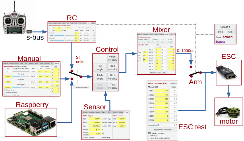
Figure. Overall data flow for the drone flight controller. Most blocks also refer to tabs in the GUI (drone_gui).
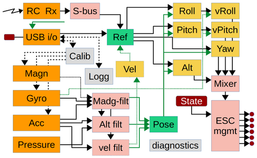
Figure. The main software functions. Orange blocks are sensor and communication io. Green if the primary measurement and reference (set-point) data (Roll, Pitch, Yaw, Height and possibly lateral velocity. Pink blocks are other software functions. Gray is for configuration and calibration. Yellow blocks are PID control. Diagnosis is mostly battery voltage, but with the capability of measuring temperature and (with internal and external sensor) and current with external sensors.
The pose holds 4 values (roll, pitch, yaw and height). The roll, pitch and yaw position is estimated by the Madgwick filter. The raw gyro values are used as velocity measurement directly and as the D-term by the angle controllers.
Calibration of the gyro and accelerometer is built in. Calibration of the magnetometer is using an external tool (saving the calibration result directly in the onboard flash for the Madgwick filter).
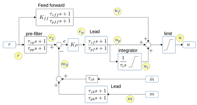
Figure. The PID control blocks all have these functionalities. The yellow circles indicate logging interfaces.
Drone control firmware
Download a copy from the SVN (subversion) repository (from a command line)
svn checkout svn://repos.gbar.dtu.dk/jcan/mobotware/drone_ctrl
If you have other repository tools, then just use the URL. The checkout create a 'drone_ctrl/trunk' directory, that has the most recent version.
The firmware is built on Arduino (Teensyduino) libraries for all low-level handling of interfaces.
Arduino version
Arduino version 1.8.13 (specifically the interrupt based ADC library for Teensy) requires at least GCC version 10 to compile.
But changing a few 'constexpr' to 'inline' in the ADC library makes it compile on GCC version 9.3 and work - maybe with a slightly larger code.
Drone control firmware
The firmware is in the "drone_ctrl" directory.
To compile the source for a Teensy 3.5 or 3.6 the Teensyduino needs to be installed after the Arduino installation.
Install Teensyduino, see https://www.pjrc.com/teensy/td_download.html . Start with installing the most recent supported version of Arduino, then overlay this by installing the Teensiduino.
Once installed the directory needs to be prepared for compilation.
Linux
make shortcut links to libraries and compiler. The shourtcut described below assumes you have installed arduino version 1.8.9 (and Teensiduino) in your home directory, change as appropriate:
cd drone_ctrl/motortest
ln -s ~/arduino-1.8.9/hardware/teensy/avr/libraries
ln -s ~/arduino-1.8.9/hardware/teensy/avr/cores/teensy3
ln -s ~/arduino-1.8.9/hardware/tools/
make
make upload
Drone firmware
The drone flight controller firmware is in the "drone_ctrl" directory.
To compile the source for a Teensy 3.5 or 3.6 the Teensiduino needs to be installed first.
Install Teensiduino, see https://www.pjrc.com/teensy/td_download.html . Start with installing the most recent supported version of Arduino, then overlay this by installing the Teensiduino.
Once installed the directory needs to be prepared for compilation.
Linux
make shortcut links to libraries and compiler. The shourtcut described below assumes you have installed arduino version 1.8.9 (and Teensiduino) in your home directory, change as appropriate:
cd drone_ctrl/drone_ctrl
ln -s ~/arduino-1.8.9/hardware/teensy/avr/libraries
ln -s ~/arduino-1.8.9/hardware/teensy/avr/cores/teensy3
ln -s ~/arduino-1.8.9/hardware/tools/
make
make upload
Control and data messages
All messages are ASCII text (7 bit) and line-oriented. Lines must be terminated with "new-line", i.e. the '\n' character ('\r' is ignored)
To and from onboard Raspberry pi
On the Raspberry Pi there is a "mission" application, that talks to the firmware and provides interface to other sensors. This software also opens a socket connection (port 24001) that can talk to the GUI.
Opti track messages drone--GUI
There is a Python based GUI for the drone_control, it is placed in the "drone_gui" directory.
Rigid body info
- To drone (request for pose data)
 sub rigid                 # get a list of all rigid bodies streamed from Optitrack
 sub rigid N               # get the pose (once) for the rigid body with ID = N
 sub rigid N A             # get the pose for ID=N repeated for each update A times. If A=-1 then data is sent continuously
 sub rigid N A B           # as above, but at maximum at this interval, B in milliseconds
- reply from drone
 optip 123456789.123 F Ft ID IDs V x y z q r s t E
 where 123456789.123 is Linux time on Raspberry in decimal seconds.
       F is frame number from Optitrack, Ft is frame time from Optitrack (in decimal seconds),
       ID is rigid body ID, IDs is number of streamed rigid bodies,
       V is 1 is the pose is valid (valid poses are sent only, except for the list),
       x,y,z  are position in meters in the Optitrack frame,
       q,r,s,t are quaternions for the pose.
       E is the estimated error
Optitrack status
- to drone (optitrack status)
 sub opti                  # get status (once)
 sub rigid A               # get repeated for each update received A times. If A=-1 then data is sent continuously
 sub rigid A B             # as above, but at maximum at this interval, B in milliseconds
- reply
optis K N # K=1 if Optitrack is connected, N is number of rigid body streamed (valid or not)


