Regbot version 5: Difference between revisions
From Rsewiki
| (5 intermediate revisions by the same user not shown) | |||
| Line 11: | Line 11: | ||
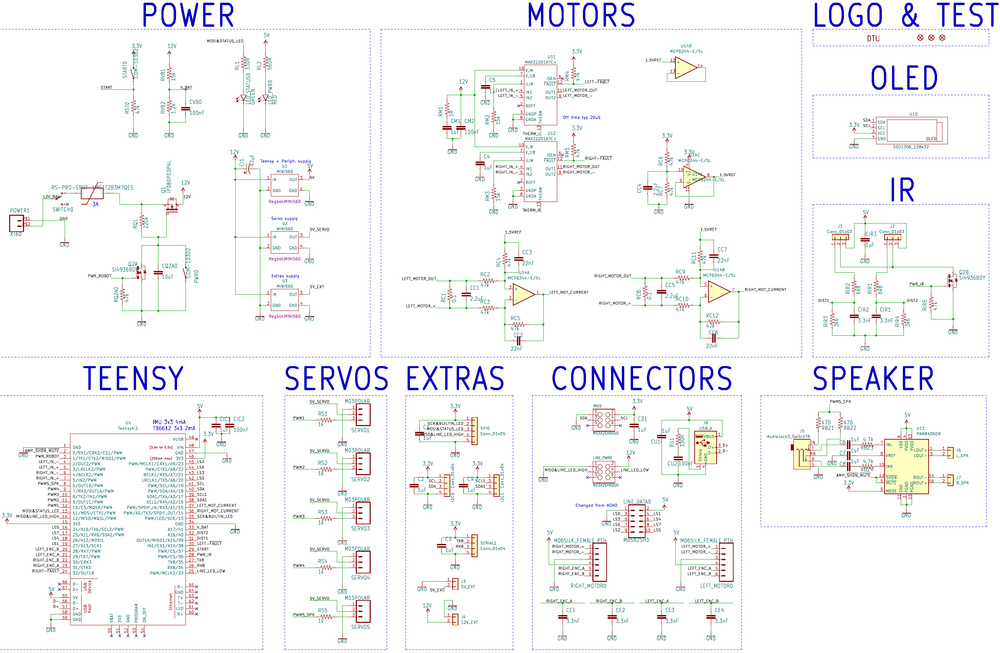
== Schematic == | == Schematic == | ||
[[File:Regbot_v5.0_schematic.png | | [[File:Regbot_v5.0_schematic.png | 1000px]] | ||
Schematic of version 5.0 (a few mods for version 5.1) | Schematic of version 5.0 (a few mods for version 5.1) | ||
=== Error list === | |||
* 5V and 12V PCB sockets, here the silk-screen indicates a wrong orientation. | |||
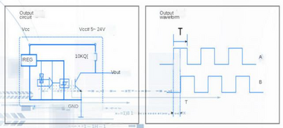
* The motor encoder delivers 5V for the encoder signals, Teensy 4.1 is not 5V tolerant (but the output is open-collector with 10kOhm to 5V, so should be OK). | |||
[[File:encoder_circuit_from_alsongdcmotor.png | 400px]] | |||
Latest revision as of 11:36, 1 November 2022
Back to Regbot
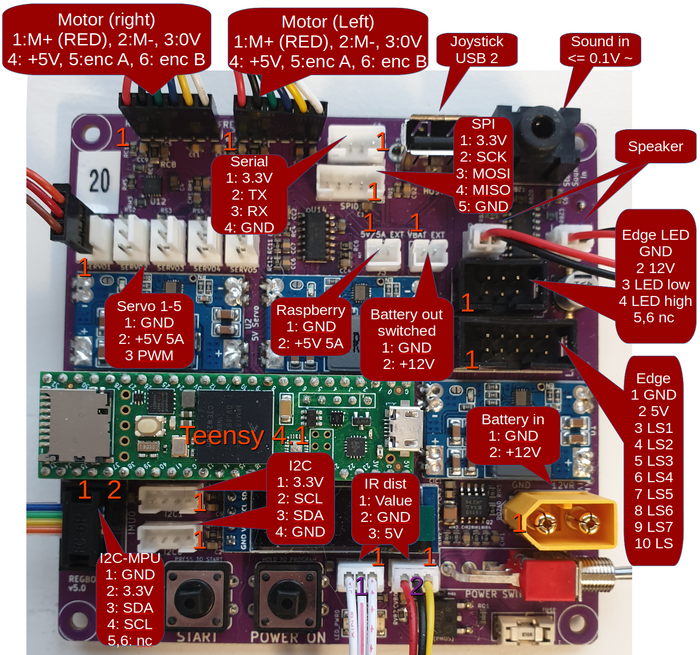
Info about Regbot PCB, diagram and plugs.
Base board
PCB layout (Version 5.1 has minor changes only)
Schematic
Schematic of version 5.0 (a few mods for version 5.1)
Error list
- 5V and 12V PCB sockets, here the silk-screen indicates a wrong orientation.
- The motor encoder delivers 5V for the encoder signals, Teensy 4.1 is not 5V tolerant (but the output is open-collector with 10kOhm to 5V, so should be OK).


