ESP8266: Difference between revisions
From Rsewiki
(Created page with "200px ==Hardware needed== For setting up the ESP8266 the following parts will be needed: * A fully functional RegBot programmed with latest version...") |
No edit summary |
||
| Line 1: | Line 1: | ||
[[File: | [[File:esp8266.jpg|300px]] | ||
==Hardware needed== | ==Hardware needed== | ||
| Line 9: | Line 9: | ||
* A capacitor for stabilizing the output from the voltage regulator. E.g. 100uF. | * A capacitor for stabilizing the output from the voltage regulator. E.g. 100uF. | ||
* A PC with an Arduino IDE installed (for easy serial communication). | * A PC with an Arduino IDE installed (for easy serial communication). | ||
==Wiring== | |||
Use a breadboard or through-hole prototype PCB to wire or solder the setup. | |||
This model of the ESP8266(-01) has 8 pins as seen on the figure below. | |||
[[File:esp8266pinout.png|400px]] | |||
Revision as of 20:20, 18 April 2016
Hardware needed
For setting up the ESP8266 the following parts will be needed:
- A fully functional RegBot programmed with latest version of the robot software. Consult this section to ensure that.
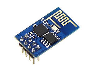
- A ESP8266 WiFi Module.
- A 5V to 3.3V voltage regulator.
- A capacitor for stabilizing the output from the voltage regulator. E.g. 100uF.
- A PC with an Arduino IDE installed (for easy serial communication).
Wiring
Use a breadboard or through-hole prototype PCB to wire or solder the setup.
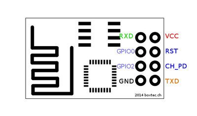
This model of the ESP8266(-01) has 8 pins as seen on the figure below.

