Flexbot design: Difference between revisions
No edit summary |
No edit summary |
||
| Line 28: | Line 28: | ||
[[File:Teensy Wheel Configuration.png|970px]] | [[File:Teensy Wheel Configuration.png|970px]] | ||
Figure 1: Schematic for the ankle configuration for the Flexbot. | Figure 1: Schematic for the ankle configuration for the Flexbot. (Click on picture for full resolution) | ||
===Open items (to-do list)=== | ===Open items (to-do list)=== | ||
| Line 49: | Line 49: | ||
[[File:Flexbot Knee Configuration.png|1000px]] | [[File:Flexbot Knee Configuration.png|1000px]] | ||
Figure 2: Schematic for the knee configuration for the Flexbot. | Figure 2: Schematic for the knee configuration for the Flexbot. (Click on picture for full resolution) | ||
===Open items (to-do list)=== | ===Open items (to-do list)=== | ||
Revision as of 12:50, 16 July 2017
Back to Flexbot main page
Design overview hardware
Each "leg" of the flexbot consists of 4 actuators.
- An angled DC motor to control the wheel.
- Two linear actuators to control the motion of the robot's body.
- A linear actuator to adjust heading angle on the wheel.
Each of the legs are interfaced and controlled by two μ-processor boards (Teensy 3.2 and 3.5). The boards are currently placed on matrix boards where other hardware components (IMU, motor driver, etc.) are accessible from. Each leg is split up in two parts which are presented as the ankle configuration and the knee configuration. The hardware design for robot's body is presented here.
A complete 3D model of the robot is available using the online CAD software Onshape.com - JCA should be contacted for sharing and editing the model.
Ankle hardware design
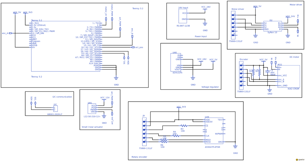
The ankle configuration currently includes:
- Angled DC motor to run the wheel - model IG42-CRGM
- SyRen 10 motor driver
- Teensy 3.2 μ-processor board
- Pololu 24V to 5V voltage regulator - model D24V22F5
- Firgelli L12-50-210-12-I linear actuator
- 14-bit rotary encoder - model AS5048A
The schematic for the ankle configuration is shown in Figure 1 and can be accessed using Upverter, a free online e-CAD design tool. Link to the project on Upverter is given here - contact JCA for editorial access.
In addition to the schematic shown it can be mentioned that a ferrite core has been introduced on the power supply wires for the DC motor. This reduces EMI which was found to greatly interfere with the encoder signals from the motor.
Figure 1: Schematic for the ankle configuration for the Flexbot. (Click on picture for full resolution)
Open items (to-do list)
This list includes items that needs to be done, but have not been finished (or started) yet. This serves as reference for where to start when catching up on the project. This list should be updated as items are finished and finished items should be moved to the list which represents the current configuration of the ankle. The responsibility of updating the schematic and git repository falls to the person responsible for carrying out the open item. This way the documentation both here and on git reflects the current state of the ankle configuration.
- The rotary encoder has been wired and tested. Connections in the schematic from the Teensy to the encoder are missing. The encoder still needs to be fixed to correct position on the wheel configuration and magnets needs to be attached to bolt fastening the spring dampener.
- A Pololu 24V to 12V needs to implemented on the matrix board to supply the small linear actuator. They are of model D24V22F12 (link to product is on git) and should be ordered but have not been received.
- The I2C interface for inter-configuration(and host)-communication should be removed from the board. USB should be used instead.
- When the final hardware configuration for the ankle has been decided upon, a revision 1 of a PCB layout should be made. Upverter holds the schematic, but footprints for layout should be carefully checked(or made).
Knee hardware design
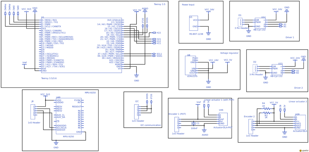
The knee configuration currently includes:
- A linear actuator to control the height (tilt) of the configuration - model DLA-12-10-A-200-POT-IP66
- Cytron 10A DC Motor Driver - model RB-Cyt-132
- MPU to obtain tilt - model MPU-9250/6500
- Teensy 3.5 μ-processor board
The schematic for the knee configuration is shown in Figure 2 and can be accessed using the free online e-CAD design tool Upverter. Link to the project on Upverter is given here - contact JCA for editorial access.
Figure 2: Schematic for the knee configuration for the Flexbot. (Click on picture for full resolution)
Open items (to-do list)
This list includes items that needs to be done, but have not been finished (or started) yet. This serves as reference for where to start when catching up on the project. This list should be updated as items are finished and finished items should be moved to the list which represents the current configuration of the knee. The responsibility of updating the schematic and git repository falls to the person responsible for carrying out the open item. This way the documentation both here and on git reflects the current state of the ankle configuration.
- A Pololu 24V to 5V needs to inserted onto the matrix board. Wiring has been made, only thing missing is the component and to solder pin headers onto the component. They are of model D24V22F5 (link to product is on git) and should be ordered but have not been received.
- A second motor driver needs to be fitted to the knee. Wiring has been made and the driver is on stock and are found in one of the two boxes containing parts for the project.
- The interface for linear actuator 1 supports the linear actuator with potentiometer feedback. This should at some point be changed to the ordered actuators with hall sensor feedback and the configuration on the matrix should be changed to reflect this as well (should be same as linear actuator 2).
- The matrix board needs to support a second MPU. It has not been investigated whether or not it can be connected to the same bus by changing the address. Maybe it would be easier to simply connect to its own I2C bus. Teensy 3.5 holds 3 I2C interfaces and currently uses 1.
- A second linear actuator should be connected to the knee. This relies on the mechanics to be finished.
- When the final hardware configuration for the knee has been decided upon, a revision 1 of a PCB layout should be made. Upverter holds the schematic, but footprints for layout should be carefully checked (or made).
Body hardware design
The design of the body hardware has not been started yet. A few ideas have been discussed bot nothing final has been decided upon. The body hardware design will first be relevant in mid/late autumn. A few discussed ideas of what the body hardware design should include are listed below:
- An Intel Nuc i7 configuration: https://www.intel.com/content/www/us/en/products/boards-kits/nuc/kits.html
- A USB hub or at least enough connections to connect all Teensy μ-processor boards. This will sum up to 8 μ-processor boards (2 on each leg).
- A main power supply. Should be 24V obtained from LiPo batteries or other mobile source.

