Motor drive PCB: Difference between revisions
From Rsewiki
No edit summary |
No edit summary |
||
| Line 8: | Line 8: | ||
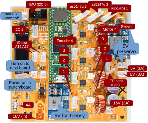
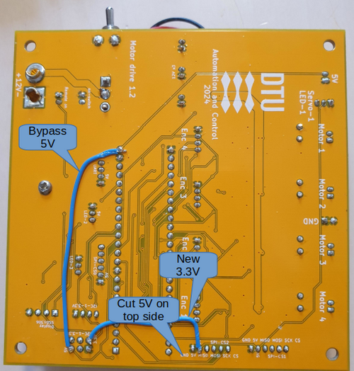
Figure 1,2. Pcb with (most) plug functions. | Figure 1,2. Pcb with (most) plug functions. | ||
[[File:power-on-mod-new-ann.png | 500px | [[File:power-on-mod-new-ann.png | 500px | Teensy circuit version 2.1]] | ||
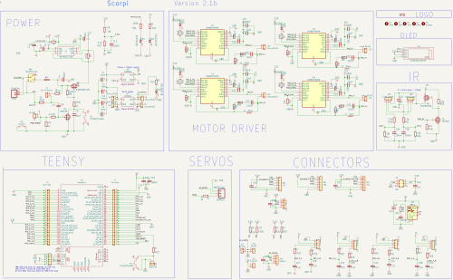
Figure 3 | Figure 3. Teensy circuit for four motor control designed for Scorpi control. | ||
=== Power on === | === Power on === | ||
Revision as of 08:17, 30 July 2024
Back to scorpi
Motor drive PCB version 1,.2
Figure 1,2. Pcb with (most) plug functions.
Figure 3. Teensy circuit for four motor control designed for Scorpi control.
Power on
Power on is modified to use an external switch. The external switch turns on one board; this board then turns on slave boards.
All bords that should turn on must have the physical switch in the on position.
To turn individual boards on, use the 'Power reset' button, with the switch on that board on and all other switches off.
Power off
Do not turn power off by operating the switch, if there is a Raspberry Pi operating on its power.
Power of should use the 'power off' command from each Raspberry, with an off delay, to allow the Raspberry to shut down nicely.


