Schematic: Difference between revisions
From Rsewiki
No edit summary |
No edit summary |
||
| Line 6: | Line 6: | ||
[[File:Schematic_2.png]] | [[File:Schematic_2.png]] | ||
Line sensor is not | There is further allowed for additional interfaces: | ||
* Line sensor - blinking LEDs at 1kHz and 8 sensors - connected to 8 A/D converters on the Teensy. | |||
* IR distance sensors (Sharp 2Y0A21F) two, that is connected to 5V and A0 (IR1) and A1 (IR2) on the processor. | |||
* Interface to Nordic Radio board with SPI interface (not in software yet) | |||
* Serial interface (Teensy pin 0 (RX1) and 1 (TX1) (not supported by software yet. | |||
Revision as of 15:32, 2 January 2016
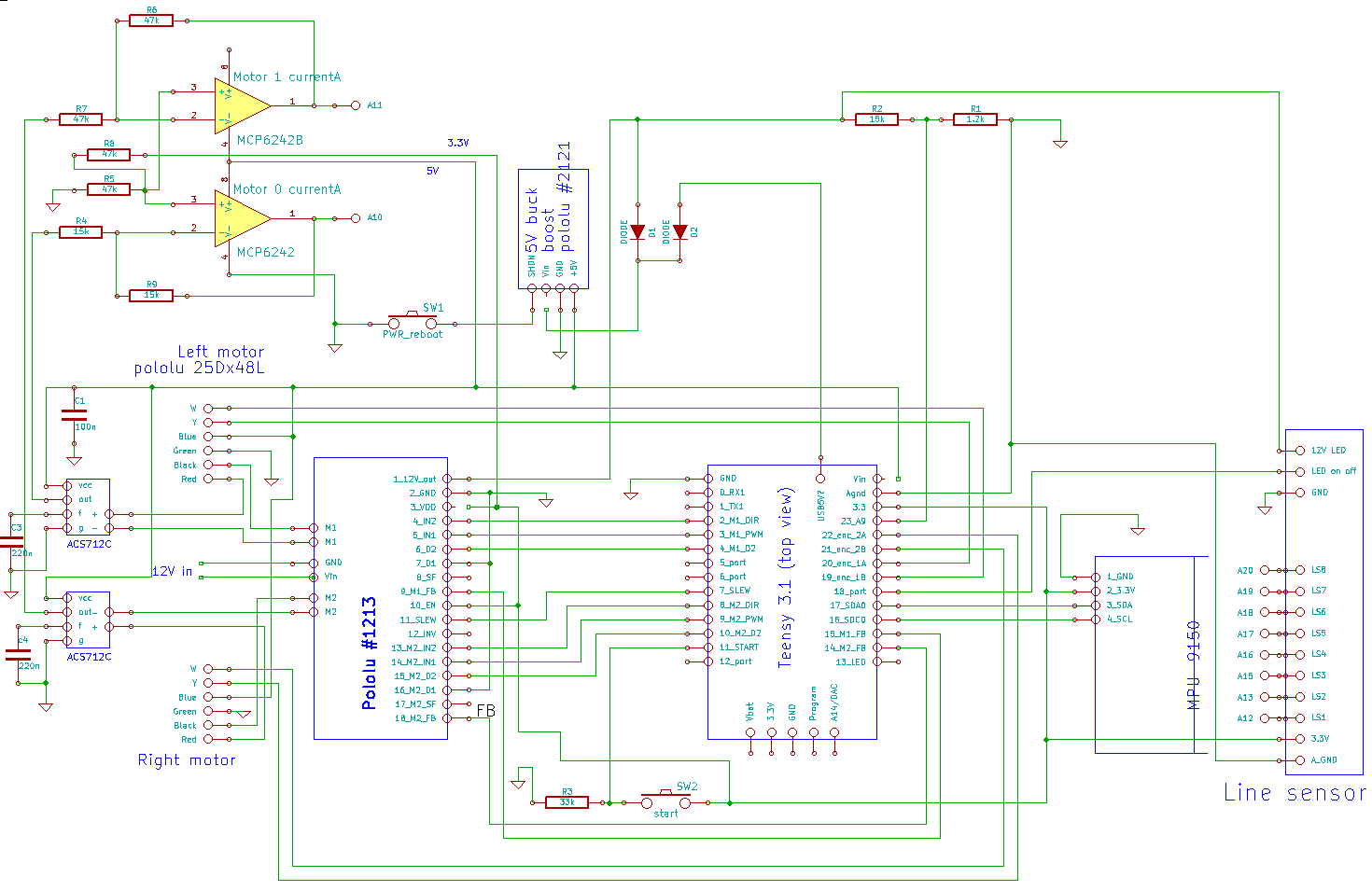
RegBot schematic revision 0.0
The teensy USB-5V connection to Vin is cut on the teensy-board, to allow 5V-PSU to supply in all cases.
There is further allowed for additional interfaces:
- Line sensor - blinking LEDs at 1kHz and 8 sensors - connected to 8 A/D converters on the Teensy.
- IR distance sensors (Sharp 2Y0A21F) two, that is connected to 5V and A0 (IR1) and A1 (IR2) on the processor.
- Interface to Nordic Radio board with SPI interface (not in software yet)
- Serial interface (Teensy pin 0 (RX1) and 1 (TX1) (not supported by software yet.
