ESP8266: Difference between revisions
From Rsewiki
No edit summary |
(→Wiring) |
||
| Line 17: | Line 17: | ||
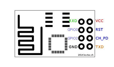
[[File:esp8266pinout.png|400px]] | [[File:esp8266pinout.png|400px]] | ||
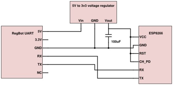
The pins need to be connected as the following schematic shows. | |||
[[File:esp8266schematic.png|600px]] | |||
The 3v3 pin on the Teensy is known to not be able to deliver enough current to the ESP8266 which needs approx 220mA. Instead the 5V pin is used which is connected directly to the RegBots 5V power supply and a voltage regulator is used to level the voltage. "Chip powerdown" and "reset" needs to be pulled up to VCC. RX goes to TX and vice versa. | |||
. | |||
Revision as of 21:05, 18 April 2016
Hardware needed
For setting up the ESP8266 the following parts will be needed:
- A fully functional RegBot programmed with latest version of the robot software. Consult this section to ensure that.
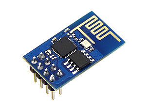
- A ESP8266 WiFi Module.
- A 5V to 3.3V voltage regulator.
- A capacitor for stabilizing the output from the voltage regulator. E.g. 100uF.
- A PC with an Arduino IDE installed (for easy serial communication).
Wiring
Use a breadboard or through-hole prototype PCB to wire or solder the setup.
This model of the ESP8266(-01) has 8 pins as seen on the figure below.
The pins need to be connected as the following schematic shows.
The 3v3 pin on the Teensy is known to not be able to deliver enough current to the ESP8266 which needs approx 220mA. Instead the 5V pin is used which is connected directly to the RegBots 5V power supply and a voltage regulator is used to level the voltage. "Chip powerdown" and "reset" needs to be pulled up to VCC. RX goes to TX and vice versa. .


