Control: Difference between revisions
(Created page with "File:Gui_control_data_points.png Figure 3. The general PID controller design with additional optional controller parts. "'''r'''" is reference input. And after the option...") |
No edit summary |
||
| Line 1: | Line 1: | ||
The main purpose of the robot is to train control theory. | |||
==Robot overview== | |||
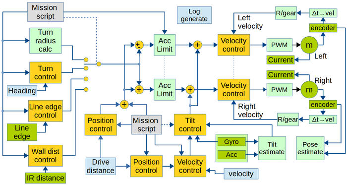
The figure gives the robot functionality with focus on control. | |||
[[File:blockdiagram_software.png|700px]] | |||
Figure 1. Overview of software data flow. Yellow is control blocks. | |||
Green is hardware (motor and sensors), Light green is calculations. Light blue is obtained values. | |||
Gray is input values. | |||
Sample time for all controllers and data values are 1ms. | |||
All software is written in c++, based on Arduino libraries. | |||
Most controllers can be switched off. I.e. if the velocity controller is switched off, then the reference input is fed directly to the output (in this case the reference input is then in Volts rather than m/s) and the acceleration limiter is bypassed too. | |||
* [[Design calculations]] | |||
==Control loop configuration== | |||
All control blocks (yellow boxes in the figure 1 above) can be configured as P, PI, P-Lead and PI-Lead controllers, with the possibility for a (1st order) prefilter, a (1st order) feed forward and a post integrator. The Lead can be implemented in the forward and return branch, and can also be used more flexible with any pole and zero combination, but all with a steady state gain of 1. | |||
[[File:Gui_control_data_points.png]] | [[File:Gui_control_data_points.png]] | ||
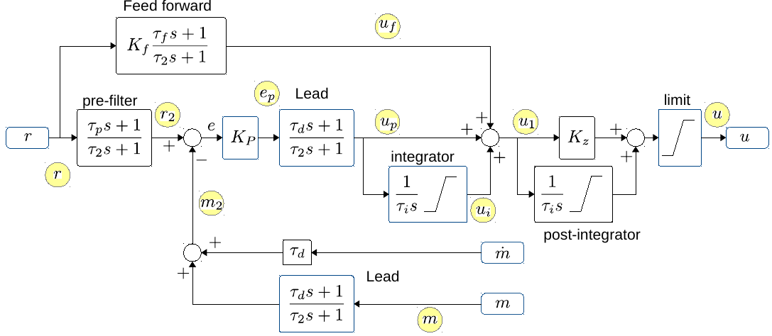
Figure | Figure 2. The general PID controller design with additional optional controller parts. "'''r'''" is reference input. And after the optional "'''pre-filter'''" the reference is compared with the measured value "'''m'''", optionally through a Lead filter. The "'''m-dot'''" is an optionally derivative of the measurement, that can be used for a less noisy Lead (with tau_d as normal, but no pole). The error signal "'''e'''" is fed through a gain "'''Kp'''", an optional Lead and an optional integrator. After this the output "'''u1'''" is summed from "'''up'''" (proportional/Lead), "'''ui'''" integrator term and "uf" from an optional feed forward branch. The output "'''u1'''" can further optionally be integrated (if '''Kz'''=0, if '''Kz'''=1 then the post-integrator has a zero). The output is finally limited to signal "'''u'''". | ||
The yellow circles indicate the datapoints that can be logged. | The yellow circles indicate the datapoints that can be logged. | ||
| Line 9: | Line 33: | ||
The "'''post-integrator'''" is (mostly) usable in the balance controller. | The "'''post-integrator'''" is (mostly) usable in the balance controller. | ||
The balance controller replaces the "'''Lead'''" after "'''m'''" with a "1", and uses tau_d after "'''m-dot'''", and "'''m-dot'''" is connected to tilt velocity from the gyro. | The balance controller replaces the "'''Lead'''" after "'''m'''" with a "1", and uses tau_d after "'''m-dot'''", and "'''m-dot'''" is connected to tilt velocity from the gyro (see also figure 1). | ||
Revision as of 07:02, 28 May 2017
The main purpose of the robot is to train control theory.
Robot overview
The figure gives the robot functionality with focus on control.
Figure 1. Overview of software data flow. Yellow is control blocks. Green is hardware (motor and sensors), Light green is calculations. Light blue is obtained values. Gray is input values.
Sample time for all controllers and data values are 1ms. All software is written in c++, based on Arduino libraries.
Most controllers can be switched off. I.e. if the velocity controller is switched off, then the reference input is fed directly to the output (in this case the reference input is then in Volts rather than m/s) and the acceleration limiter is bypassed too.
Control loop configuration
All control blocks (yellow boxes in the figure 1 above) can be configured as P, PI, P-Lead and PI-Lead controllers, with the possibility for a (1st order) prefilter, a (1st order) feed forward and a post integrator. The Lead can be implemented in the forward and return branch, and can also be used more flexible with any pole and zero combination, but all with a steady state gain of 1.
Figure 2. The general PID controller design with additional optional controller parts. "r" is reference input. And after the optional "pre-filter" the reference is compared with the measured value "m", optionally through a Lead filter. The "m-dot" is an optionally derivative of the measurement, that can be used for a less noisy Lead (with tau_d as normal, but no pole). The error signal "e" is fed through a gain "Kp", an optional Lead and an optional integrator. After this the output "u1" is summed from "up" (proportional/Lead), "ui" integrator term and "uf" from an optional feed forward branch. The output "u1" can further optionally be integrated (if Kz=0, if Kz=1 then the post-integrator has a zero). The output is finally limited to signal "u".
The yellow circles indicate the datapoints that can be logged.
All integrators can be limited. The integrators are further disabled if the output limiter limits the output. Some of the control interfaces (all but the balance controllers) further disables integrators when there is defined an acceleration limit in the mission, and this actually is limiting the acceleration.
The "post-integrator" is (mostly) usable in the balance controller.
The balance controller replaces the "Lead" after "m" with a "1", and uses tau_d after "m-dot", and "m-dot" is connected to tilt velocity from the gyro (see also figure 1).

