Flexbot design: Difference between revisions
No edit summary |
No edit summary |
||
| Line 22: | Line 22: | ||
* Angled DC motor to run the wheel - model IG42-CRGM | * Angled DC motor to run the wheel - model IG42-CRGM | ||
* SyRen 10 motor driver - see [[Syren 10A motorcontroller| Syren 10A motorcontroller]] | * SyRen 10 motor driver - see [[Syren 10A motorcontroller| Syren 10A motorcontroller]] | ||
* Firgelli L12-50-210-12-I linear actuator | * Firgelli L12-50-210-12-I linear actuator | ||
==Knee hardware design== | ==Knee hardware design== | ||
| Line 52: | Line 30: | ||
* MPU to obtain tilt - model MPU-9250/6500 | * MPU to obtain tilt - model MPU-9250/6500 | ||
* Teensy 3.5 μ-processor board | * Teensy 3.5 μ-processor board | ||
* Pololu 24V to 5V voltage regulator - model D24V22F5 | |||
* Pololu 24V to 12V voltage regulator - model D24V??F12 - for steering actuator | |||
===Open items (to-do list)=== | ===Open items (to-do list)=== | ||
This list includes items that needs to be done, but have not been finished yet. This serves as reference for where to start when catching up on the project. This list should be updated as items are finished and finished items should be moved to the list which represents the current configuration of the knee. The responsibility of updating the schematic and git repository falls to the person responsible for carrying out the open item. This way the documentation both here and on git reflects the current state of the ankle configuration. | This list includes items that needs to be done, but have not been finished yet. This serves as reference for where to start when catching up on the project. This list should be updated as items are finished and finished items should be moved to the list which represents the current configuration of the knee. The responsibility of updating the schematic and git repository falls to the person responsible for carrying out the open item. This way the documentation both here and on git reflects the current state of the ankle configuration. | ||
* The encoder counts for the DC motor at the ankle is still giving issues after ferrit cores. | * The encoder counts for the DC motor at the ankle is still giving issues after ferrit cores. | ||
Revision as of 15:38, 12 February 2018
Back to Flexbot main page
Design overview hardware
Each "leg" of the flexbot consists of 4 actuators.
- An angled DC motor to control the wheel.
- Two linear actuators to control the motion of the robot's body.
- A linear actuator to adjust heading angle on the wheel.
Each of the legs are interfaced and controlled by two μ-processor boards (Teensy 3.2 and 3.5). The boards are currently placed on matrix boards where other hardware components (IMU, motor driver, etc.) are accessible from. Each leg is split up in two parts which are presented as the ankle configuration and the knee configuration. The hardware design for robot's body is presented here.
A complete 3D model of the robot is available using the online CAD software Onshape.com - JCA should be contacted for sharing and editing the model.
Each leg part is connected with a two parallel stretches (mostly carbon tubes), each 4 carbon tubes, from foot to knee and from knee to hip (see also Flexbot 3D print).
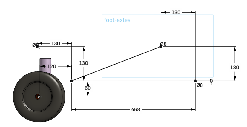
Figure 1. Basic geometry.
Ankle hardware design
The ankle configuration currently includes:
- Angled DC motor to run the wheel - model IG42-CRGM
- SyRen 10 motor driver - see Syren 10A motorcontroller
- Firgelli L12-50-210-12-I linear actuator
Knee hardware design
The knee configuration currently includes:
- A linear actuator to control the height (tilt) of the configuration - model DLA-12-10-A-200-POT-IP66
- Cytron 10A DC Motor Driver - model RB-Cyt-132
- MPU to obtain tilt - model MPU-9250/6500
- Teensy 3.5 μ-processor board
- Pololu 24V to 5V voltage regulator - model D24V22F5
- Pololu 24V to 12V voltage regulator - model D24V??F12 - for steering actuator
Open items (to-do list)
This list includes items that needs to be done, but have not been finished yet. This serves as reference for where to start when catching up on the project. This list should be updated as items are finished and finished items should be moved to the list which represents the current configuration of the knee. The responsibility of updating the schematic and git repository falls to the person responsible for carrying out the open item. This way the documentation both here and on git reflects the current state of the ankle configuration.
- The encoder counts for the DC motor at the ankle is still giving issues after ferrit cores.
Body hardware design
The design of the body hardware has not been started yet. A few ideas have been discussed bot nothing final has been decided upon. The body hardware design will first be relevant in mid/late autumn. A few discussed ideas of what the body hardware design should include are listed below:
- An Intel Nuc i7 configuration: https://www.intel.com/content/www/us/en/products/boards-kits/nuc/kits.html
- A USB hub or at least enough connections to connect all Teensy μ-processor boards. This will sum up to 8 μ-processor boards (2 on each leg).
- A main power supply. Should be 24V obtained from LiPo batteries or other mobile source.
