PCB: Difference between revisions
From Rsewiki
No edit summary |
No edit summary |
||
| Line 6: | Line 6: | ||
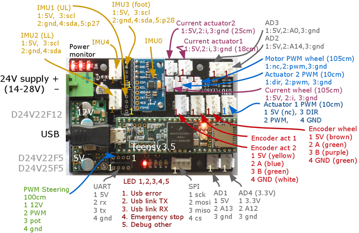
Figure 1. Plug names and pin allocation for Teensy board. | Figure 1. Plug names and pin allocation for Teensy board. | ||
MPU0, on-board, SCL0, pin 18-19, AD0=NC. | |||
MPU1, SCL1, pin 37_38-19, AD0=HIGH. | |||
MPU1, SCL1, pin 37_38-19, AD0=NC. | |||
MPU3, SCL2, pin 3_4, AD0 = HIGH. | |||
MPU3, SCL2, pin 3_4, AD0 = NC. | |||
[[File:leg_teensy-block-function.png | 700px]] | [[File:leg_teensy-block-function.png | 700px]] | ||
Revision as of 19:47, 22 April 2018
Flexbot PCBs
Teensy board
Figure 1. Plug names and pin allocation for Teensy board. MPU0, on-board, SCL0, pin 18-19, AD0=NC. MPU1, SCL1, pin 37_38-19, AD0=HIGH. MPU1, SCL1, pin 37_38-19, AD0=NC. MPU3, SCL2, pin 3_4, AD0 = HIGH. MPU3, SCL2, pin 3_4, AD0 = NC.
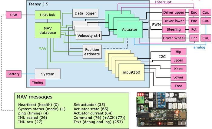
Figure 2. Functional blockdiagram og Teensy controller board. Not all blocks and MAV messages are implemented yet.
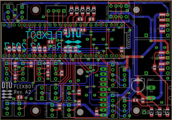
Figure 3. Layout of PCB (designed in Eagle).
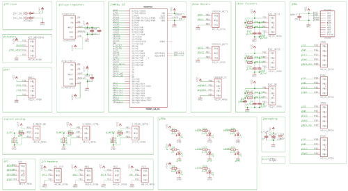
Figure 4. PCB schematic - click on image to get better view.


