Getting started: Difference between revisions
(→WiFi) |
(→Status) |
||
| Line 33: | Line 33: | ||
===Status=== | ===Status=== | ||
Once connected the robot time and name is shown in green (figure 1). Below the green frame is a frame to start and stop missions. | Once connected the robot time and name is shown in a green frame (figure 1). Below the green frame is a frame to start and stop missions. | ||
The start button is a replication of the green button on the robot. | The start button is a replication of the green button on the robot. | ||
The "Load" field shows how much time the robot uses for every sample ( | The "Load" field shows how much time the robot uses for every sample (the robot samples all sensors and calculations every 1ms), so the load should be less than 1000ns at all times. | ||
When the configuration or mission is changed it can be saved to a small flash disk (2kB) on the robot with the "save to flash" button. | When the configuration or mission is changed it can be saved to a small flash disk (2kB) on the robot with the "save to flash" button. | ||
Revision as of 19:21, 31 December 2018
Back to Regbot main page.
GUI
The GUI is a python-QT application used to configure the REGBOT. Runs under Windows (regbot.exe) or Linux (regbot.py, but requires the right python packages to be installed first)
Connect
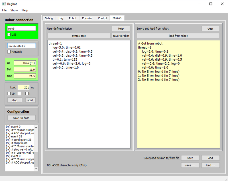
The GUI looks like shown here in figure 1.
Figure 1. REGBOT GUI, then top-left frame controls the connection. Etiher communication over an USB com-port or using WiFi.
USB
Connect USB cable and figure out which COM port is created for the robot (NB! each robot connected to the PC has probably reserved a COM-port number). The control panel may help.
In figure 1 the robot has created COM6:.
WiFi
At DTU the robots attempt to connect to the DEVICE WiFi access point (SSID=device), it may take 20 seconds to establish the connection.
Each robot has a reserved IP:
10.16.166.XXX
Where XXX is the robot number. The robot Thea has number 51, so its IP number is 10.16.166.51.
A number of remarks and debug messages (shown in the lower left frame in figure 1) will not be send over WiFi (lower bandwidth).
Status
Once connected the robot time and name is shown in a green frame (figure 1). Below the green frame is a frame to start and stop missions. The start button is a replication of the green button on the robot.
The "Load" field shows how much time the robot uses for every sample (the robot samples all sensors and calculations every 1ms), so the load should be less than 1000ns at all times.
When the configuration or mission is changed it can be saved to a small flash disk (2kB) on the robot with the "save to flash" button.
Menu
The menus has some extra features.
Help
Most fields has explanations, when the mouse hoovers over the field.
Control configuration
This is a control exercise robot, so some control must be configured to run missions.
Control is configured from the control tab - see also User_interface#Controller_configuration.
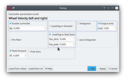
The velocity control is the most important, and in the dialog shown below in figure 2, set the values in the figure text.
Figure 2. A Kp = 0, but enabled is fine if "Feed forward" Kf = 4. Set output limit to 9V and disable the "Lead/lag in feedback" and all other settings. This will translate a mission velocity of 0.5 m/s by a factor 4 to a motor voltage of 2 Volt, which in turn approximately gives a velocity of 0.5 m/s.

