Motor drive PCB: Difference between revisions
From Rsewiki
No edit summary |
No edit summary |
||
| Line 5: | Line 5: | ||
[[File:motor_drive_PCB-top-ann.png | 500px]] | [[File:motor_drive_PCB-top-ann.png | 500px]] | ||
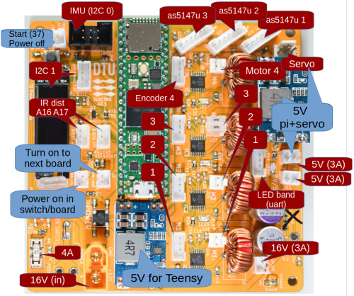
Figure 1,2. Pcb with | Figure 1,2. Pcb version 2.1 with plug usage. | ||
[[File:power-on-mod-new-ann.png | 500px | Teensy circuit version 2.1]] | [[File:power-on-mod-new-ann.png | 500px | Teensy circuit version 2.1]] | ||
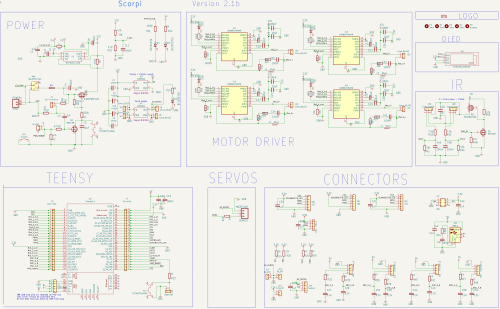
Figure 3. Teensy circuit for four motor | Figure 3. Teensy circuit version 2.1 for four motor controls. | ||
=== Power on === | === Power on === | ||
Power on is | Power on is designed to use an external power-on switch. | ||
The external switch turns on one board; this board then turns on slave boards. | The external switch turns on one board; this board then turns on slave boards. | ||
The physical on-off switch is shorted in on-position. | |||
=== Power off === | === Power off === | ||
Raspberry Pi initiates turn off, which orders Teensy (boards) to turn off after the Raspberry shutdown. | |||
A request power off button will tell the Raspberry that it is time to shut down. | |||
Revision as of 08:31, 30 July 2024
Back to scorpi
Motor drive PCB version 1,.2
Figure 1,2. Pcb version 2.1 with plug usage.
Figure 3. Teensy circuit version 2.1 for four motor controls.
Power on
Power on is designed to use an external power-on switch. The external switch turns on one board; this board then turns on slave boards.
The physical on-off switch is shorted in on-position.
Power off
Raspberry Pi initiates turn off, which orders Teensy (boards) to turn off after the Raspberry shutdown. A request power off button will tell the Raspberry that it is time to shut down.

