Regbot encoder analysis: Difference between revisions
No edit summary |
No edit summary |
||
| Line 5: | Line 5: | ||
[[file:regbot_encoder_delay.png]] | [[file:regbot_encoder_delay.png]] | ||
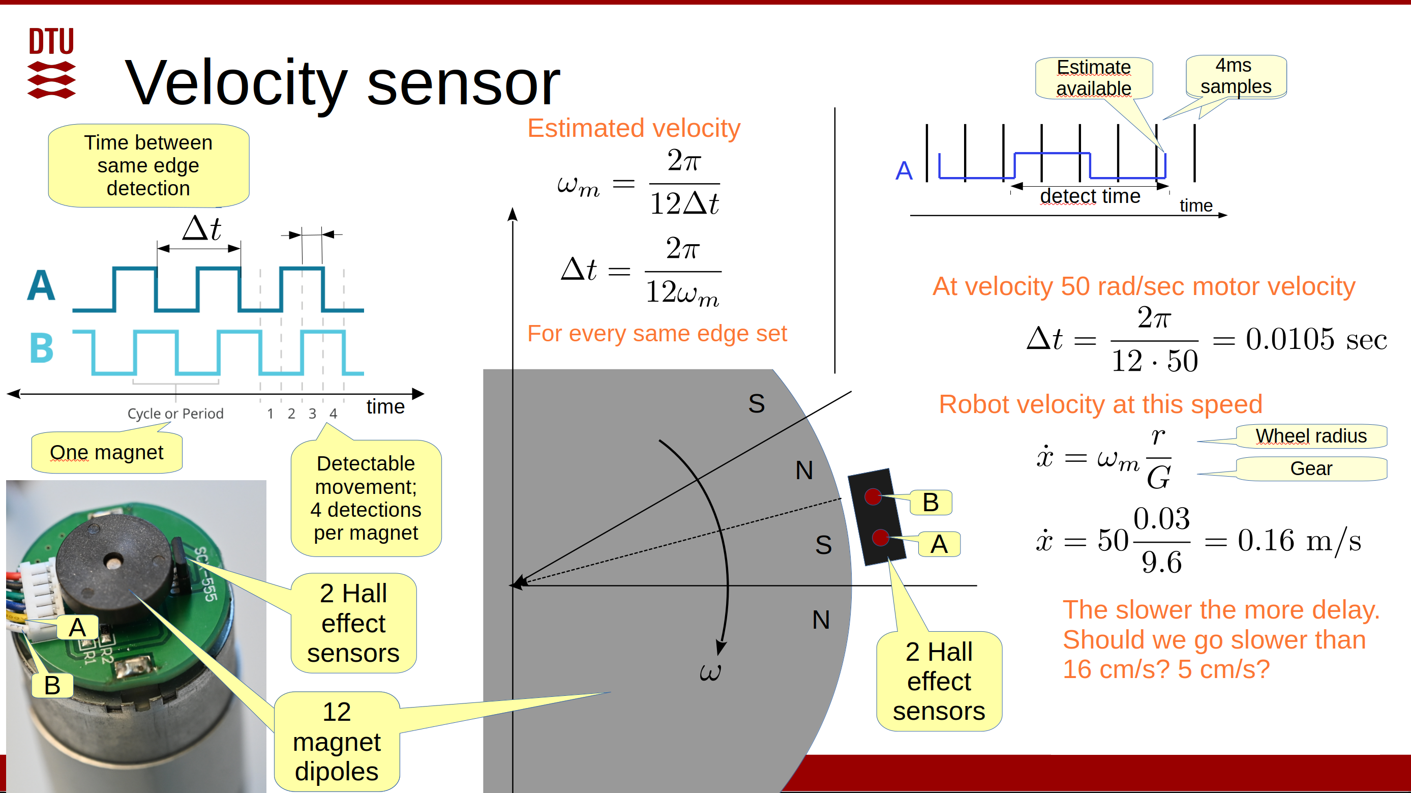
The encoder has 12 magnets and two HAL sensors. The sensors have a separation and position that should give symmetric A and B signals, as shown. If all magnet dipoles have exactly the same size and strength, then velocity can be estimated using the time between any two flanks. But this is not the reality. | |||
A more stable velocity is obtained using the time between the same flank on the same signal, e.g. the rising flank on the A signal. This gives a velocity estimate at every flank, but the velocity is estimated over a longer time. | |||
The average delay is half the time between two equal flanks on the same signal plus the time since the flank was detected. | |||
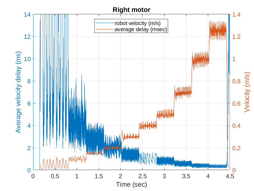
The following plot tests this. A fast PI velocity controller is used to obtain stable velocities between 0.05 and 1.3 m/s. The motor gear is 9.6:1, and the wheel radius is 0.03m. | |||
[[file:encoder_delay.png]] | [[file:encoder_delay.png]] | ||
The magnetic encoder is used to calculate motor (and robot) velocity | The magnetic encoder is used to calculate motor (and robot) velocity, which is estimated based on the time between encoder ticks. | ||
At a robot velocity of 5 cm/sec, the average delay is often more than 30 ms. The velocity controller is not well designed for this delay. | |||
The velocity is more stable at 10 cm/sec, and the average delay is less than 10 ms. | |||
At 0.5 m/sec and faster, a repeating pattern is visible. This pattern is related to the velocity and is repeated for every motor rotation. This indicates that the magnets in the encoder are not totally equal. | |||
Revision as of 14:25, 28 November 2024
Regbot encoder issues
The Regbot motors use a magnetic encoder at the motor axle, as shown below.
The encoder has 12 magnets and two HAL sensors. The sensors have a separation and position that should give symmetric A and B signals, as shown. If all magnet dipoles have exactly the same size and strength, then velocity can be estimated using the time between any two flanks. But this is not the reality.
A more stable velocity is obtained using the time between the same flank on the same signal, e.g. the rising flank on the A signal. This gives a velocity estimate at every flank, but the velocity is estimated over a longer time.
The average delay is half the time between two equal flanks on the same signal plus the time since the flank was detected.
The following plot tests this. A fast PI velocity controller is used to obtain stable velocities between 0.05 and 1.3 m/s. The motor gear is 9.6:1, and the wheel radius is 0.03m.
The magnetic encoder is used to calculate motor (and robot) velocity, which is estimated based on the time between encoder ticks.
At a robot velocity of 5 cm/sec, the average delay is often more than 30 ms. The velocity controller is not well designed for this delay.
The velocity is more stable at 10 cm/sec, and the average delay is less than 10 ms.
At 0.5 m/sec and faster, a repeating pattern is visible. This pattern is related to the velocity and is repeated for every motor rotation. This indicates that the magnets in the encoder are not totally equal.

