Design overview
Design overview hardware
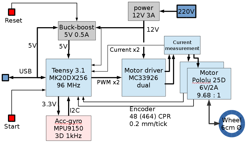
Regbot consist of a microprocessor board (teensy 3.1/3.2) that controls 2 motors (Pololu 25D) through a motor driver (MC33926). Motor rotation data is collected from motor encoders. Motor current is avaiable and there is further a gyro-accelerometer sensor (see figure 1 below).
The processor is supplied with 5V from either USB or from a 12V battery or power supply.
A reset button disables the power - and therefore initiates a reboot.
The robot is differential controlled, where a difference in velocity between left and right wheel generates a turn.
The processor is an ARM MK20DX256 processoren (a 32bit 96MHz microprocessor) and is programmed to implement a number of control loops that is able to control some basic movements of the robot.
Figure 1. Hardware blockdiagram. Most blocks are off-the-shelf hardware modules from PJRC (Teensy), Pololu (motor, driver and buck-boost converter) and Sparkfun (IMU).
Other sensors like an edge detector (edge of a tape line on the floor), IR distance sensors (Sharp 2Y0A21 type) and wireless radio communication may be implemented on some of the robots.
Design overview software
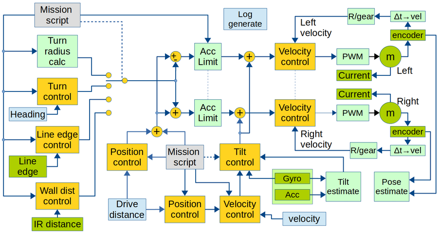
The robot software is shown as a block diagram in figure 2 below.
Figure 2. Overview of software data flow. Yellow is control blocks. Green is hardware (motor and sensors), Light green is calculations. Light blue is obtained values. Gray is input values.
Sample time for all controllers and data values are 1ms. All software is written in c++, based on Arduino libraries.
Most controllers can be switched off. I.e. if the velocity controller is switched off, then the reference input is fed directly to the output (in this case the reference input is then in Volts rather than m/s) and the acceleration limiter is bypassed too.
PCB connections revision 2B
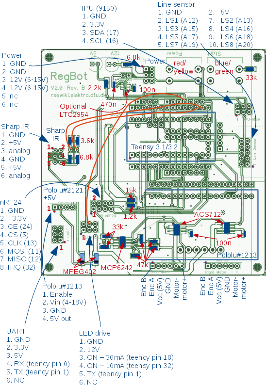
Component placement and values (in red) are shown here. Plug connections are shown in blue.
Figure 3. The Sharp IR sensor output is not connected to an AD converter input.
The IR sensor voltage divider output should be between 0 and 1.2V, and could be connected to A0 and A1 (used to be feedback from motor-controller). Unfortunately a plug can not be mounted (space conflict with USB plug).
The orange wires are patches (line sensor low power at pin 32 and from IR sensor to A0 and A1).
Install hardware - version 1A
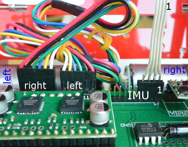
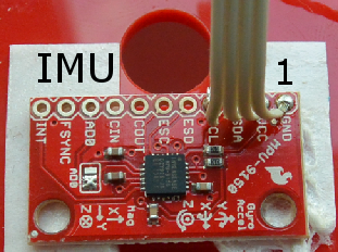
The motor and IMU wires are mounted as shown here. The IMU uses 4 wires only, so only the rightmost pins (1..4) on the main board are used.
Pin 1 on the IMU is as shown here
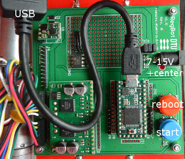
The teensy processor and power is connected as shown
