ESP8266
By Jesper H. Christensen
Hardware needed
For setting up the ESP8266 the following parts will be needed:
- A fully functional RegBot programmed with latest version of the robot software. Consult this section to ensure that.
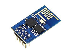
- A ESP8266 WiFi Module.
- A 5V to 3.3V voltage regulator.
- A capacitor for stabilizing the output from the voltage regulator. E.g. 100uF.
- A FTDI cabel with 3v3 for serial communication.
- A PC with an Arduino IDE installed (for easy serial communication).
Initial setup
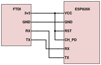
Connect the FTDI cable to the ESP8266 as shown below.
Connect the FTDI to a PC and open up an Arduino IDE.
1. Choose the correct serial port from the Tools > Serial Port menu.
2. Open the Serial Monitor via the Tools menu or "magnifying glass" icon on the editor window.
3. For the later firmware versions, ensure Both NL & CR is selected in the line ending pop-up menu at the bottom of the serial monitor. (For earlier versions it must be set to Carriage return.)
4. Default firmware version uses 115200 baud as communication speed.
When turning on the device the objective is to see some characters followed by ready. Never mind if the characters are rubbish as long as ready shows in the end. If this is not achieved check the wiring and play around with the baud rate or/and line ending until success, as it might vary with firmware versions.
Connecting to WiFi
When success has been achieved in the last section AT-commands can be send to modify the module.
- Start by typing (still in serial comm. on the Arduino IDE) AT. The response should be OK.
- Check the firmware version by typing AT+GMR.
- Enable the module to both act as station and access point by typing AT+CWMODE=3. Response should be OK.
- Join a WiFi access point by typing AT+CWJAP="<access_point_name>","<password>" e.g. AT+CWJAP="dtuDummyNet","dummyPass" and check if the module got an IP with AT+CIFSR.
If the above has been done successfully the ESP8266 is now connected to the desired WiFi access point, and will remember this access point even if the module is restarted.
Setup as TCP Server
1. Enable multiple connections by typing AT+CIPMUX=1.
2. Set the module to listen for a connection on a specific port (in this case port 1336) AT+CIPSERVER=1,1336.
3. From another device on the same network connect to the listening port, e.g. with telnet via Putty. The module should display Link.
4. Type some text into the telnet session, e.g. RegBots are cool!.
5. The module should display following +IDP,0,17:RegBots are cool! with 0 being the connection channel and 17 being the length of the received data.
6. Send some data in response with the CIPSEND command AT+CIPSEND=0,13 where 0 is the channel and 13 the length of the data. The module will display the prompt > and the data is to be typed and send Yes they are!.
7. The telnet session should display Yes they are!.
Setting up a TCP server must be done with every restart unlike accessing a known WiFi access point which is done automatically after being connected once.
Wiring
Use a breadboard or through-hole prototype PCB to wire or solder the setup.
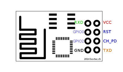
This model of the ESP8266(-01) has 8 pins as seen on the figure below.
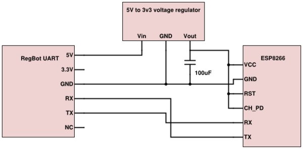
The pins need to be connected as the following schematic shows.
The 3v3 pin on the Teensy is known not to be able to deliver enough current to the ESP8266 which can draw approx 220mA at the most. Instead the 5V pin is used which is connected directly to the RegBots 5V power supply and a voltage regulator is used to level the voltage. "Chip powerdown" and "reset" needs to be pulled up to VCC. RX goes to TX and vice versa.
Utilization
To utilize the ESP8266 connected to the Teensy board simply initialize the ESP8266 module as a serial connection just like normal. After initialization AT commands can be send just like in the above sections. E.g. given in the RegBot software there is a serial1_send_str method and the desired command to send is AT+CIPMUX=1 do:
serial1_send_str((char*)"AT+CIPMUX=1\r\n");
and preferably create a method that waits for the response so that the module is ready to receive the next command.
A very important note is that when using the CIPSEND command to transmit data from the server to the client, the client must respond. Otherwise the server will continue to think that it is in "send-mode" and will keep on transmitting until the client has responded.


