REGBOT version 3
Aim
- maintain frame,
- Avoid too many satellite PCB's,
- more powerfull 5V,
- fix PCB errors on version 2,
- new servo interface plug
- battery saver - turn OFF if battery voltage is low.
- battery saver - turn IR sensor off if not used.
Status and observations
- Line sensor low power pin (Teensy pin 25) now working. Pin 25 set to output in main.cpp (line 125), and pulsed in main.cpp (line 425 and 466). Line estimate seems OK (after calibration) - line sensor calibration missing in regbot.ini.
Missing/bugs
Software robot side (Teensy)
- control implement test of edge, wall and forward distance controllers - partially tested (velocity, heading, position and balance seems OK)
- wifi - is OK after a reboot,but stops after a few minutes, if no wifi client is attached. Sometimes also if used.
- AD converter for "servo" 4 and 5 (when not output pins) is not implemented, and should be available as continue condition in missions.
- Line sensor hardware 2 missing low-power.
Software client side
- Servo debug page is a mess with edit/apply/cancel, as most actions work instantaneously.
- Servo status in client is wrong after change.
- Help in control dialogue is missing - should refer to wiki page.
Plugs
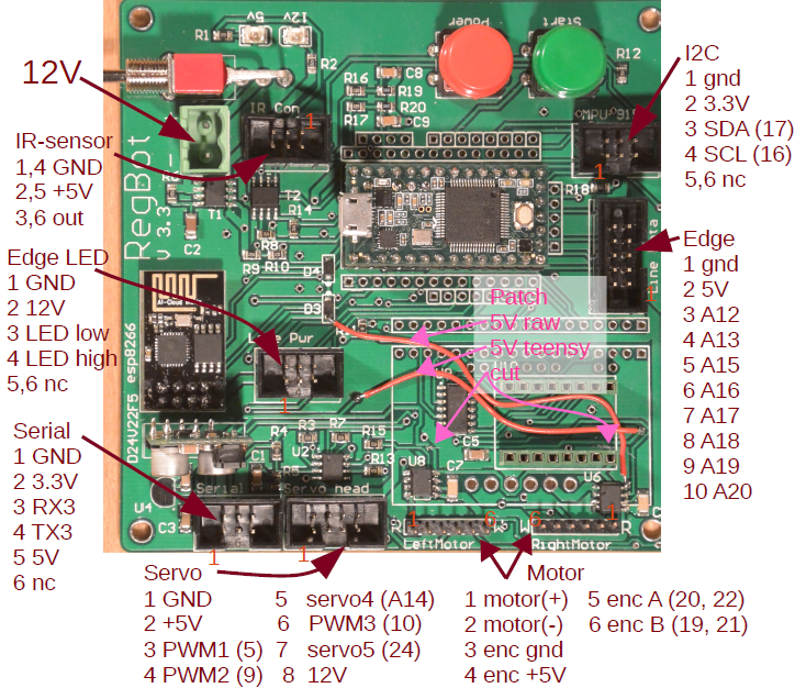 Figur1 1 (above) shows plug configuration on hardware version 3.
Teensy pin assingnment
GND side
- 0 serial RX (wifi)
- 1 serial TX (wifi)
- 2 motor left direction
- 3 motor left PWM
- 4 motor left D2 enable -> flyttes til right motor PWM
- 5 servo pin 3 (PWM) - og 2nd SPI CS pin (4) (see also teensy pin 24)
- 6 Start button
- 7 motor slew ctrl -> ny RX3 (ekstra seriel forbindelse)
- 8 motor -> ny TX3 (ekstra seriel forbindelse)
- 9 motor right PWM -> flyttes til servo PWM (servo pin 4) på hardware 3 -> pin 9 ny servo 2 PWM
- 10 motor right D2 enable - > flyttes til servo PWM (servo pin 6) på hardware 3 -> pin 10 ny servo 3 PWM
- 11 SPI MOSI -> ny motor enable (D2) på hardware 3
- 12 SPI MOSI -> ny right motor direction
Vin side
- 13 heart beat LED og SPI clock -> ny: kun heart beat LED
- 14 (A0) IR dist 2
- 15 (A1) IR dist 1
- 16 I2C SCL
- 17 I2C SDA
- 18 Line sensor LED power
- 19 encoder left B
- 20 encoder left A
- 21 encoder right B
- 22 encoder right A
- 23 (A9)battery voltage
End
- A14 (analog out) servo pin 5 (i/o, ikke PWM) - for analog in or analog signal out
2nd row
- A10 motor current left
- A11 motor current right
button side
- A12 line sensor pin 3
- A13 line sensor pin 4
- A15 line sensor pin 5
- A16 line sensor pin 6
- A17 line sensor pin 7
- A18 line sensor pin 8
- A19 line sensor pin 9
- A20 line sensor pin 10
- 24 SPI CE (SPI CS pin (pin 3)) -> ny digital I/O pin på servo block (hardware 3)
- 25 Line sensor LED HIGH
- 32 IR power on - hardware 3 (line sensor low power on hardware 2)
- 33 Robot power on
Message to-from regbot
PID control message
All controlls is formatted with 26 values, and looks like this example (balance)
cbal 1 -3 0 1 9999.99 1 0 1 1 1 0.029 0.001 0 1 1 1 0.1 5 1 0 1 0 1 1 1 99.99
The indivitual numbers are - after the controller keyword (here 'cbal'):
 1 cbal 1 // use (any part of controller)
 2     -3 // Kp
 3      0 1 9999.99 1 // integrator (use, tau, limit, (and_zero - not implemented))
 7      0 1 1 // lead forward (use, zero, pole)
 10     1 0.029 0.001 // lead backward (use, zero, pole)
 13     0 1 1 // pre-filt (use, zero, pole)
 16     1 0.1 5 1 // post integrator (use, tau, limit, and_zero)
 20     0 1 // feed forward (use, Kff)
 22     0 1 1 // feed forward pole-zero (use zero pole)
 25     1 99.99 // output limit (use, limit)
The other controllers uses keywords (parameters are the same as above):
- cvel wheel velocity control
- ctrn Heading control
- cwve IR sensor forward distance controller
- cwth IR sensor follow wall controller
- cpos Position controller (non balance)
- cedg Line edge controller
- cbal Balance angle controller
- cbav Velocity controller - in balance
- cbap Position controller - in balance (not implemented)
Rebuild pictures
Hardware version 1 rebuild
Regbot number 1 to 15 - needs a new (version 3) motherboard.
Fro
It need to be installed with
- motors
- new battery,charger,IMU mount, and
- battery
- charger
- IMU - from old hardware, with new 6-pin plug >(pin 1..4 used only (I2C))
- New IR sensors (2) with cables fitted into a 6-pin plug.
- New frame (white or black)
- USB cable refit
- New labels
hardware version 2 rebuild
Hardware 2 comes in 2 flavours, one with a 7805 5V power supply and one with a switch-mode power supply.
With 7805
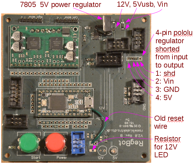
Hardware with 7805 power regulator, as shown in figure below.
Figure 2 (above) show the original configuration for hardware version 2 with 7805 regulator. This is to be replaced with a Pololu buck-boost converter (surplus from hardware 1 robots).
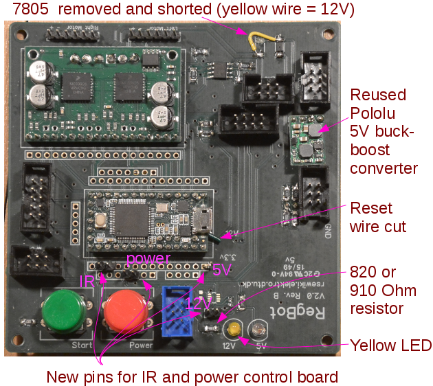
In addition they should be supplied with a yellow LED and a 910 (or 820) Ohm resistor (yellow is a 12V color (in standard PC power supplies).
There should be mounted new pins for new Power and IR sensor board (wires on the back needs to be removed first).
The 5V pin (for the IR sensor) is to have a zig-zag shape to connect to the left-most socket on the power-IR-sensor board.
Figure 3 (above) shows the modified top-side of main board.
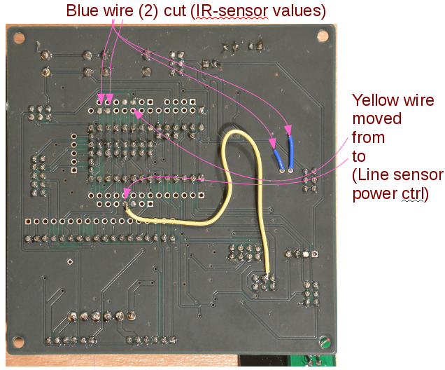
Figure 4 (above) is the back side of hardware 2 configuration, there the 2 blue wires should be cut (for old IR-sensor plug).
The yellow wire (Line sensor high power) should be moved to the shown pin on other side of Teensy.
Without 7805
This configuration has the desired power supply, so change the connections on the back and the new pins for the power and IR sensor board only.
Hardware 3 modifications
The hardware 3 comes in 2 versions: with a big motor driver board (expensive and slow) and a small motor driver board (cheaper and faster).
Both has a problem with power noise from power drain for wifi module from the 4.75V supply for the Teensy to the motor current sensor (visible on all logging of motor current). Therefore the power to the current sensors should be moved to the 5V output of the Pololu 5V converter.
This is shown in figure below:
 Figure 5 (above), Two traces on the PCB is cut, to isolate supply to current sensor. Pin 8 on one of the current sensors are then connected to the anode of the diode from 5V supply to 4.75V to teensy (and wifi). The two sides of the cut power trace are then reconnected to give (4.75V) to the line sensor electronics.
On hardware version 3 with small (fast) motor controller, this induces too much noise on the motor encoder lines, and filter capacitors need to be mounted on the encoder lines.
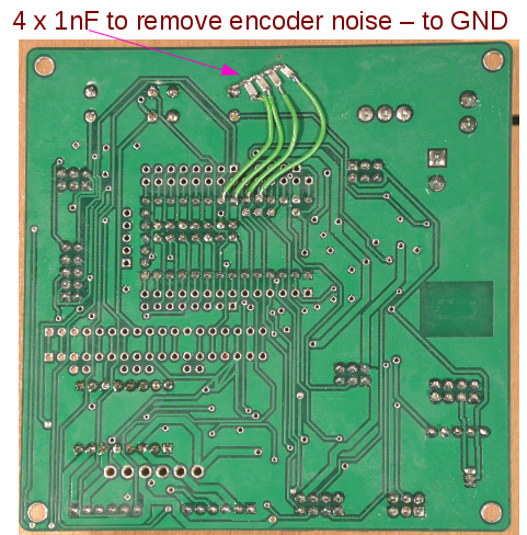 Figure 6 (above) shows the 4 filter capacitors - each 1nF - connected to the 4 encoder input lines on the teensy as shown, the other end of capacitors are connected to ground.
