Wheel encoder
Wheel encoders are intended on all 4 motors, replacing the brake.
Initially rear motors are mounted with encoders. The encoders are of type AS5057 12 bit magnetic encoders.
Additionally encoder A and B signals are forwarded, but not enabled.
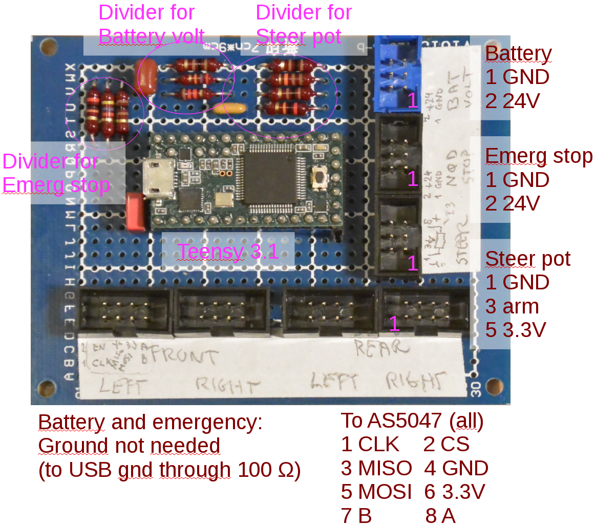
Encoder interface is I2C and interfaced using a Teensy 3.1 processor, as shown in figure 1.
Figure 1. Breadboard with Teensy 3.1 and 4 8-pin connectors to the AS5047 boards. The board also holds the needed voltage dividers for battery voltage and steering potentiometer.
Signal wires to encoders has a 100 Ohm serial resistor (CLK, MISO, MOSI (and CS on rear encoders))
Voltage dividers
The Teensy AD converter for battery voltage and steering potentiometer uses 1.2V reference. The signals therefore needs voltage dividers.
Battery
The battery voltage divider uses a 27kOhm and a 1.2kOhm, allowing up to 28.2V to be measured. (in (optional) ground connection is mounted a 100 Ohm resistor to avoid or limit ant ground current). There is a filter capacitor of 390nF.
Steering potentiometer
The steering potentiometer is supplied from 3.3V supply (through 100 Ohm resistors). The arm is then voltage divided using a 20kOhm and 11kOhm resistors, with a filter capacitor of 330nF.
Emergency stop
This is intended to inform software that emergency stop is pressed - pt. only one channel for rear emergency stop, but maybe the remote should be separate.
A voltage divider is added on the emergency line with 20kOhm and 4.7kOhm, this should give a switch voltage of about 7V - assuming supply from 24 V.
