Regbot settings
Back to Robobot.
This is some suggestions for changed settings for Robobot.
Using the regbot configuration GUI.
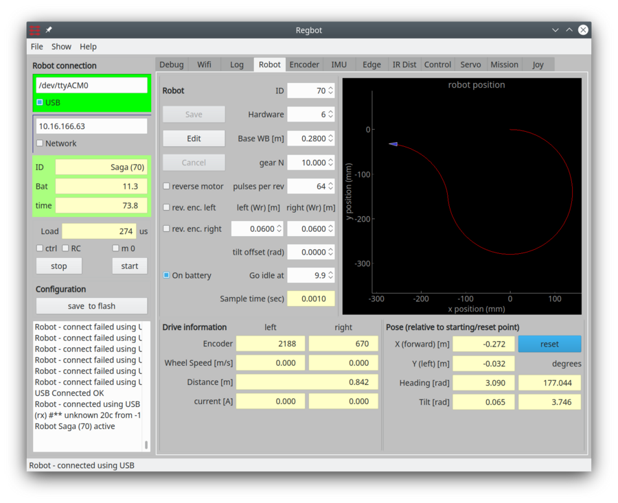
Robot configuration
Metric setup
The main items are:
- Hardware version: 6 in all cases
- Wheelbase WB: The distance between centres of the driving wheels (0.2 to 0.3m)
- Gear N:1: Motor dependant, we have N=10, N=18 and N=30.
- Pulses per revolution: 64 on all TS-37GB-555 motors.
- Wheel radius: dependent on the wheels (0.03 to 0.08m)
Most settings require 'Edit' to be pressed prior to any change.
Use 'Save' and 'Save to flash' in this order to save the changes, also after a reboot.
Other settings:
- Reverse motor, 'rev.enc.left', 'rev.enc.right' should not be ticked.
- Tilt offset: a value in radians, that could offset the reported tilt angle (0.0 is fine).
- Go idle at: To keep the battery safe, this value should not be less than 9.9V.
Line sensor
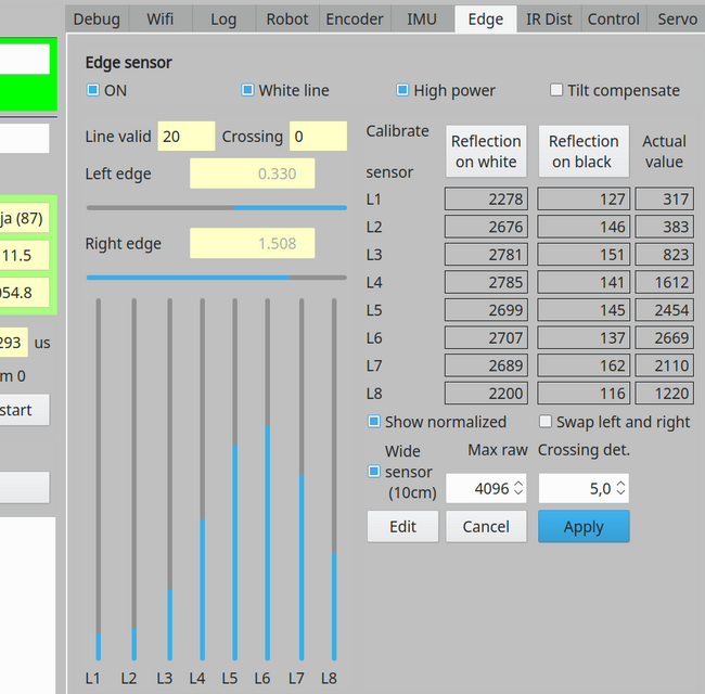
The line sensor should be calibrated with a white paper (or tape line) and either a black line or looking into nothing. After that "show normalized" should all sensors show about 75%.
Crossing detect should be ?
Figure 2. Line sensor calibration GUI, and line sensor PCB.
Figure 3. schematics. Each sensor, a BPW46, is biased by transistor, QN1, and the signal amplified and filtered through QP1, the output is LS0 and feed to a Teensy AD converter. VDD is 5V. The LEDs are pulsed 0.5ms on, 0.5ms off. each set of 3 LEDs is controlled by one constant current transistor. 12V is battery voltage.
IMU calibrate
The gyro can be calibrated only. Let the robot stand still and press the calibrate button.
NB! the axis orientation depends on the position of the IMU chip, and may not be intuitive.
Control issues
Some examples of control settings.
Velocity control works fine with "Feed forward" = 4 and a Kp = 15 - and keep the output limit = 9V (or less).
Edge control
For higher speed in the range 0.7-0.9 m/s the following control settings could be used.
With the new 10cm line sensor optimal setting is not found, a kp=0.1 - 0.15 seems OK, output limit should not be set. Here are two sets of settings that could be used, both with relative short distance from robot rotation point and the sensor (4-7cm) longer distance should have lower Kp gain.
 Thomas Marcussen - bsc project
The control uses a Lag-controller to decrease the static gain by a factor 5 (a pole with a time constant of 1.5 sec and a zero with a time constant of 0.3 seconds). This means that the high frequency gain is Kp*0.3/1.5 = 0.06.
A test script to could be:
thread=1
   vel=0.01, acc=5.0, log=50.0: time=0.2
   vel=0.9, edger=1, white=0: dist=10.0, xb=20
   vel=0,event=7 : xb<10
   :vel< 0.1
   vel=-0.3,tr=0.1:turn=60
   vel=0.3,tr=0.1:turn=60
   vel=-0.3,tr=0.1:turn=60
   vel=0.7, edger=-1, white=0: dist=10.0, xb=20, log=0
The mission follows right side of line,
- in a left curve (1mØ) until crossing a line
- wait for crossing line to disappear,
- and velocity reach 0
- make a 3-point 180 degree turn
- follow the other side of line - now a right curve (until log is full or 10 meters or crossing another black line)
The difference between a left and a right curve is the "edger=1.0" and "edger=-1.0", this makes the robot follow the curve with an offset of 1cm towards the center of the curve (more left in a left curve). This gives more space for overshoot when hitting the curve - the sensor range is about +/- 2cm.
If the line is no longer valid, then the last curvature is maintained, i.e. there is a chance that the the line will be re-found.
Heading control
Heading control is not used during a tr=xx based turn, but after such a turn the heading control maintains the end heading. The end heading is the start heading plus the turned angle.
While driving straight, then the heading control attempts to keep the heading.
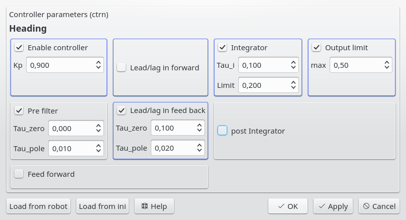
Heading control is somewhat speed dependent, these parameters seems to be good at about 0.6 m/s.
Figure 3. Heading control parameters for OK turns at a velocity of about 0.6 m/s. The controller is a PI-Lead controller with a weak pre-filter.
A 20 degree turn with an acceleration limit of 1m/s^2 and a turn radius of 0.2m makes a turn like this:
Figure 4. The log starts at about 0.55 seconds and the turn starts 0.1 seconds hereafter. The dotted line is the resulting heading, the magenta line is the target heading (when not in a turn. The red curve is the mission line number in the script below. As the acceleration is rather slow (1m/s^2) the the turn radius is not reached when half the turn is reached, so at this time the turn is deemed finished, so that there is time to recover. At this time the heading control is reengaged, and takes the heading to the desired 20 degrees. The x-axis is in seconds and the y axis in degrees. The red mission curve is line number in the script below.
This curve is generated with the following script:
thread=6
   : time=0.01
   vel=0.6, acc=1.0: dist=0.1,time=1
   log=3.0: time=0.1
   tr=0.2: turn=20.0
   : dist=0.3, log=0
Distance sensor
(missing)


