Drone control hardware
From Rsewiki
back to Drone control
Flight controller
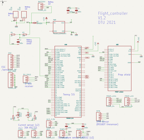
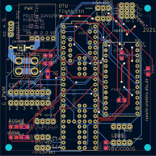
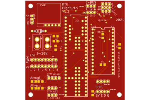
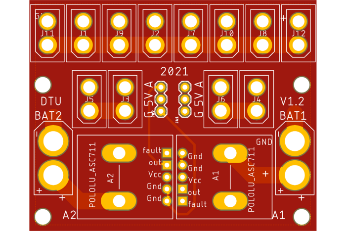
Version 1.2 schematic and PCB-layout. Sonar height is connected to RX4 same pin as A12 (marked as A12 on board) and 5V. Angle IMU for motor angles are GY91 boards connected to I2C-2, using pin 3 (SCL) and 4 (SDA) marked on board as ESC 1 (SCL) and ESC2 (SDA), both on 3.3V from pins marked A13 and 3.3V. Current measurements are not used (one is shorted). ESC 1 and 2 are moved to ESC 7 and 8.
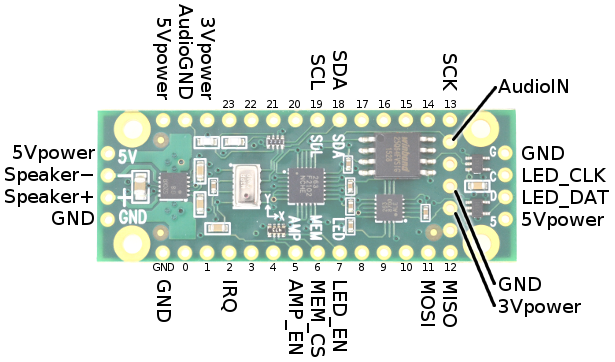
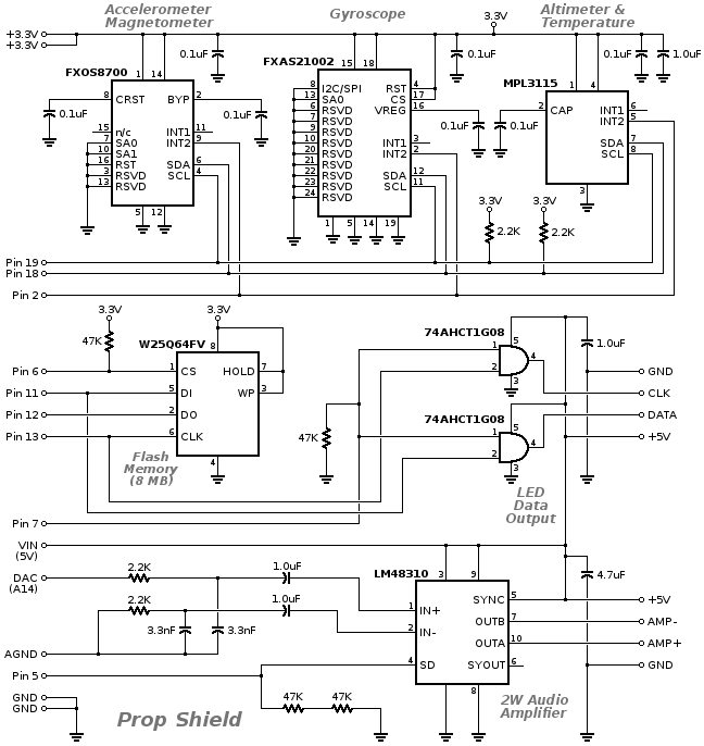
Prop Shield
From: https://www.pjrc.com/store/prop_shield.html
Signal	  Pin #	Used By:	Description
SDA	  18	sensors	I2C Data for motion sensors
SCL	  19	sensors	I2C Clock for motion sensors
IRQ	  2	sensors	Interrupt from motion sensors
MOSI	  11	memory,led	SPI Data
MISO	  12	memory	SPI Data
SCK	  13	memory,led	SPI Clock
MEM_CS	  6	memory	Low to access memory
LED_EN	  7	led	High to send LED data
LED_DAT  -	led	5v buffered LED Data output
LED_CLK  -	led	5v buffered LED Clock output
AMP_EN	  5	amp	High to enable amplifier
AudioIN  DAC	amp	Audio signal
AudioGND AGND	amp	Audio ground
Speaker+ -	amp	Connect a 4Ω or 8Ω speaker
                       Twisted pair wire is recommended
Speaker  -	-	amp
5Vpower  VIN	amp,led
3Vpower  3.3V	sensors,memory
GND	  GND	(all)
Schematic
Sensor board
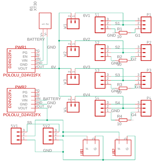
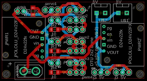
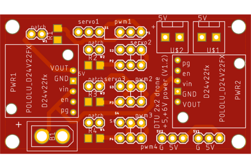
Servo power board
Interface and power board for servos
Power distribute
Power distribution from 2 batteries in parallel using XT60, all output sockets are XT30.
