|
|
| (164 intermediate revisions by 2 users not shown) |
| Line 1: |
Line 1: |
| Small robot intended for control-1 exercises.
| |
|
| |
|
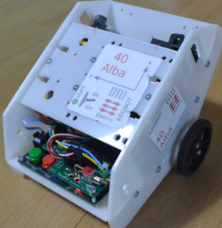
| [[File:regbot-final.png|200px]] | | REGBOT is a small robot designed for exercises for our linear control 1 course (PID control) ([http://www.dtu.dk/english/Service/Phonebook/Person?id=14453 author]). |
|
| |
|
| ==Software download==
| | [[file:foto_of_Alba_40.png | 250px]] |
|
| |
|
| *Robot software (regbot.hex): 2.124
| | Figur 1. Version 2 of Regbot. |
|
| |
|
| *Client software for windows (regbot.exe): 2.124
| | == Overview == |
|
| |
|
| (as of September, 2015)
| | This section is intended for users. |
|
| |
|
| repository for software - client and robot
| | [[Getting started]] with REGBOT GUI. |
|
| |
|
| * client: svn://repos.gbar.dtu.dk/jcan/regbot/qtgui
| | [[User interface]], how to configure the robot using the Regbot client. |
| * robot: svn://repos.gbar.dtu.dk/jcan/regbot/regbot
| |
|
| |
|
| On a Linux computer do something like this:
| | [[Control]] overview gives some information on control possibilities. |
| svn co svn://repos.gbar.dtu.dk/jcan/regbot/regbot .
| |
| svn co svn://repos.gbar.dtu.dk/jcan/regbot/qtgui .
| |
|
| |
|
| ==Install software==
| | [[Mission]], how to write a mission. |
|
| |
|
| Get the regbot.exe from the course homepage, place it in a directory, this directory will be default for configuration file and result files from the robot.
| | [[Regbot calibration]] for better performance. |
|
| |
|
| A driver must be installed to get in contact with the robot - see [[installation in windows]]
| | [[Regbot maintenance]] for longer life. |
|
| |
|
| The driver will create a com-port when connected - most likely com3 or any higher number.
| | [[Regbot GUI]] installation. |
| When the robot is disconnected by unplugging the cable, then the client needs to be restarted if it was connected when the cable was unplugged (no connection detect in windows).
| |
|
| |
|
| * [[Software installation]] and tool-chain - Linux
| | [[Regbot hardware board]]. |
| * [[installation in windows]] some of the tool-chain
| |
| * [[Schematic]]
| |
|
| |
|
| | == Install notes == |
|
| |
|
| ==User interface==
| | This section is primarily installation notes and more detailed descriptions not usually needed by the end-user. |
|
| |
|
| The user interface can configure and run the robot, as well as inspecting almost all values on the robot. Written in python using Qt GUI library.
| | [[Regbot command interface]] - command list. |
|
| |
|
| [[File:Gui_rev0.png]] | | [[Software installation]] on REGBOT (Arduino) and tool-chain - Linux |
|
| |
|
| The GUI allows to make step responses for velocity and turn. The step response is recorded in a buffer on the robot and is fetched in a MATLAB style file (as shown).
| | [[Regbot old stuff]] |
| Interface points that are recorded can be switched on and off to better utilize the limited buffer size on the robot (35kBytes).
| |
| | |
| [[File:Gui_ctrl_rev_1.png]] | |
| | |
| This is a page to make a step response and insert controller values for velocity control. The same controller is used for both wheels.
| |
| | |
| ==Design overview hardware==
| |
| | |
| [[File:blockdiagram_rev2.png]]
| |
| | |
| Hardware blockdiagram.
| |
| Most blocks are off-the-shelf hardware modules from PJRC (Teensy), Pololu (motor, driver and buck-boost converter) and Sparkfun (IMU).
| |
| | |
| A line sensor is planned, but not implemented yet.
| |
| | |
| ==Design overview software==
| |
| | |
| [[File:blockdiagram_software.png|900px]]
| |
| | |
| Overview of software data flow. Yellow is control blocks (or estimation filter).
| |
| Green is hardware (motor and sensor), Light green is calculations. Light blue is obtained values.
| |
| Gray is input values.
| |
| | |
| Sample time for all controllers and data values are 1ms.
| |
| All software is written in c++, based on Arduino libraries.
| |
| | |
| | |
| * [[Design calculations]]
| |
| | |
| ==Install hardware==
| |
| | |
| The motor and IMU wires are mounted as shown here.
| |
| The IMU uses 4 wires only, so only the rightmost pins (1..4) on the main board are used.
| |
| | |
| [[File:motor-imu-wire.png]]
| |
| | |
| Pin 1 on the IMU is as shown here
| |
| | |
| [[File:imu-wire.png]]
| |
| | |
| The teensy processor and power is connected as shown
| |
| | |
| [[File:teensy-annotated.png]]
| |
