Basebot modules: Difference between revisions
| (7 intermediate revisions by the same user not shown) | |||
| Line 1: | Line 1: | ||
Back to [[Basebot]] | Back to [[Basebot]] | ||
== | == Main code == | ||
The [[Basebot main code]], in basebot_6.ino, is described here. | |||
The main | The microprocessor only has one kernel; thus, nothing happens in parallel (except for interrupts). | ||
The main loop, therefore, calls all needed functions one at a time in each sample period. | |||
Any spare time (waiting for the next sample time) is used to listen to the USB connection. | |||
Several support modules are coded in C++ and included (#include "u...") in the main code; some of these are described below. | |||
== Support modules == | |||
==== Motor ==== | ==== Motor ==== | ||
[[file:wiki-bb-motor.png | 400px]] | [[file:wiki-bb-motor.png | 400px]] | ||
The Regbot/Basebot motor is of the type JGA25-370. | |||
The motor action is implemented in ''src/umotor.cpp'' in function ''motorSetAnchorVoltage()''. | The motor action is implemented in ''src/umotor.cpp'' in function ''motorSetAnchorVoltage()''. | ||
| Line 89: | Line 31: | ||
The motor current uses a HAL sensor ACS714; the zero is about 3.3V/2. Other nearby components may influence the values and should be used with caution. | The motor current uses a HAL sensor ACS714; the zero is about 3.3V/2. Other nearby components may influence the values and should be used with caution. | ||
The encoder uses an interrupt for every value edge. The velocity is estimated based on the timing difference from the last edge before this sample period to the newest edge. | The encoder uses an interrupt for every value edge. The velocity is estimated based on the timing difference from the last edge before this sample period to the newest edge. The squarewave from the A and B sensors is not entirely symmetric, and the distance between sensors A and B doesn't match half a magnet size. Therefore, the velocity is calculated separately for sensors A and B and the positive and negative transitions. These four velocities are then combined into a single motor velocity. | ||
When the motor runs slow, all estimates calculated from encoder values suffer some delay. | |||
For controller design, a transport delay of 10ms is usually sufficient. In Matlab, delay can be added to a transfer function as inputDelay or outputDelay. | |||
More info can be found here [[Regbot encoder analysis]]. | |||
Encoder values are available as | Encoder values are available as | ||
| Line 132: | Line 79: | ||
[[file:wiki-bb-power.png | 400px]] | [[file:wiki-bb-power.png | 400px]] | ||
The power is turned off when the | The power is turned off when the voltage drops below 10 Volts (assuming a three-cell Lipo battery). | ||
To turn the power back on, press the power button. | To turn the power back on, press the power button. As long as the button is pressed, the power will stay on regardless of the battery voltage. | ||
The P-MOS acts as the power switch and supplies battery voltage to the motor controllers and the 5V buck converter. The voltage is measured using pin A17. | The P-MOS acts as the power switch and supplies battery voltage to the motor controllers and the 5V buck converter. The voltage is measured using pin A17. | ||
When the USB is connected and the power is off, the USB 5V will power the robot. Even the motors can run (slowly) on USB power. | When the USB is connected and the power is off, the USB 5V will power the robot. Even the motors can run (slowly) on USB power. | ||
See [[Regbot encoder analysis]] for some measurements. | |||
The start button is available on pin 37. Value is high when the button is pressed. | The start button is available on pin 37. Value is high when the button is pressed. | ||
Latest revision as of 13:54, 28 November 2024
Back to Basebot
Main code
The Basebot main code, in basebot_6.ino, is described here.
The microprocessor only has one kernel; thus, nothing happens in parallel (except for interrupts). The main loop, therefore, calls all needed functions one at a time in each sample period. Any spare time (waiting for the next sample time) is used to listen to the USB connection.
Several support modules are coded in C++ and included (#include "u...") in the main code; some of these are described below.
Support modules
Motor
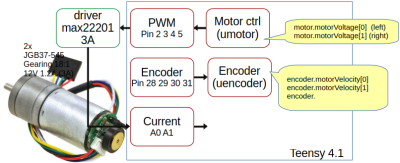
The Regbot/Basebot motor is of the type JGA25-370.
The motor action is implemented in src/umotor.cpp in function motorSetAnchorVoltage().
Motor voltage is translated to a PWM at 65kHz, where the average value corresponds to the set motor voltage. Current battery voltage is taken into consideration.
PWM = motorVoltage * MAX_PWM/(battery_voltage - voltageLoss)
The motor controller has a minimum pulse width. A minimum PWM is added to compensate if the motor voltage is not zero. The minimum corresponds to 0.4V motor voltage.
The motor current uses a HAL sensor ACS714; the zero is about 3.3V/2. Other nearby components may influence the values and should be used with caution.
The encoder uses an interrupt for every value edge. The velocity is estimated based on the timing difference from the last edge before this sample period to the newest edge. The squarewave from the A and B sensors is not entirely symmetric, and the distance between sensors A and B doesn't match half a magnet size. Therefore, the velocity is calculated separately for sensors A and B and the positive and negative transitions. These four velocities are then combined into a single motor velocity.
When the motor runs slow, all estimates calculated from encoder values suffer some delay. For controller design, a transport delay of 10ms is usually sufficient. In Matlab, delay can be added to a transfer function as inputDelay or outputDelay.
More info can be found here Regbot encoder analysis.
Encoder values are available as
encoder.encoder[0..1]  A, unsigned 32-bit, counter of all edges detected. Positive is counterclockwise.
encoder.motorVelocity[0..1] Motor velocity (float) in radians per second before the gearbox. Positive is counterclockwise.
encoder.gear is the gearbox ratio (9.68)
encoder.pulsPerRev is the number of edges on a motor revolution (48)
If no edge is detected in this sample period, the time since the last edge is used, but only if this time gives a slower estimate.
The encoder estimates are implemented in src/uencoder.cpp.
Gyro and accelerometer
The sensor chip is an MPU9250. Sensor values are extracted from the chip at every sample time, but the values may be repeated if the sample time is faster than 1 ms.
The values are available as
imu2.gyro[0..2] for rotation velocity around axis x,y,z in degrees per second.
imu2.acc[0..2]  for acceleration along x,y,z. X is forward, Y is left, and Z is up.
The values are not compensated for the mounted position. Open the robot to see the device mounting.
(implemented in uimu2.cpp)
Display
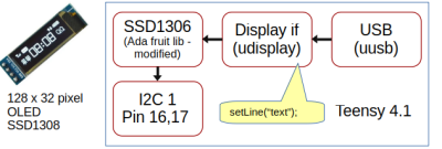
The small O-LED display has one line (at the top) that the user can set.
It is implemented in src/udisplay.cpp.
Power and start button
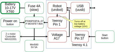
Power is managed in an attempt to avoid destroying the LiPo batteries.
The power is turned off when the voltage drops below 10 Volts (assuming a three-cell Lipo battery).
To turn the power back on, press the power button. As long as the button is pressed, the power will stay on regardless of the battery voltage.
The P-MOS acts as the power switch and supplies battery voltage to the motor controllers and the 5V buck converter. The voltage is measured using pin A17.
When the USB is connected and the power is off, the USB 5V will power the robot. Even the motors can run (slowly) on USB power.
See Regbot encoder analysis for some measurements.
The start button is available on pin 37. Value is high when the button is pressed.


