Regbot hardware board: Difference between revisions
From Rsewiki
(Created page with "Back to Regbot Back to Basebot === Circuit diagram === 900px Figure 3. The Regbot circuit. === PCB - 3D view === 900px === PCB === Figure 4. Ecpected view of PCB. 900px Figure 5. PCB with more trace details.") |
No edit summary |
||
| Line 8: | Line 8: | ||
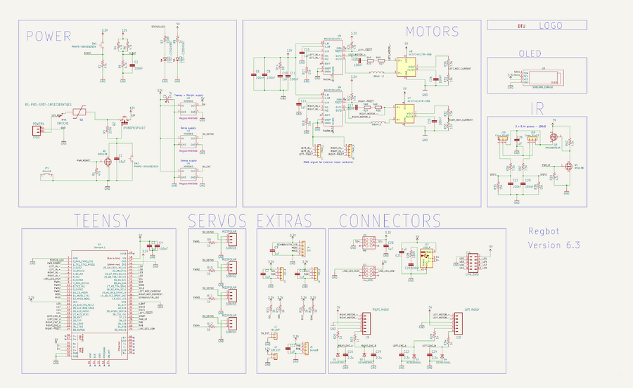
[[File:regbot_6.3.png | 900px]] | [[File:regbot_6.3.png | 900px]] | ||
Figure | Figure 1. The Regbot circuit. | ||
=== PCB - 3D view === | === PCB - 3D view === | ||
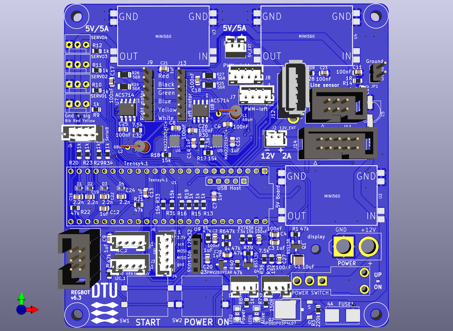
[[File:regbot_6.3_PCB.png | 900px]] | [[File:regbot_6.3_PCB.png | 900px]] | ||
Figure 2. 3D view from KiCad. | |||
=== PCB === | === PCB === | ||
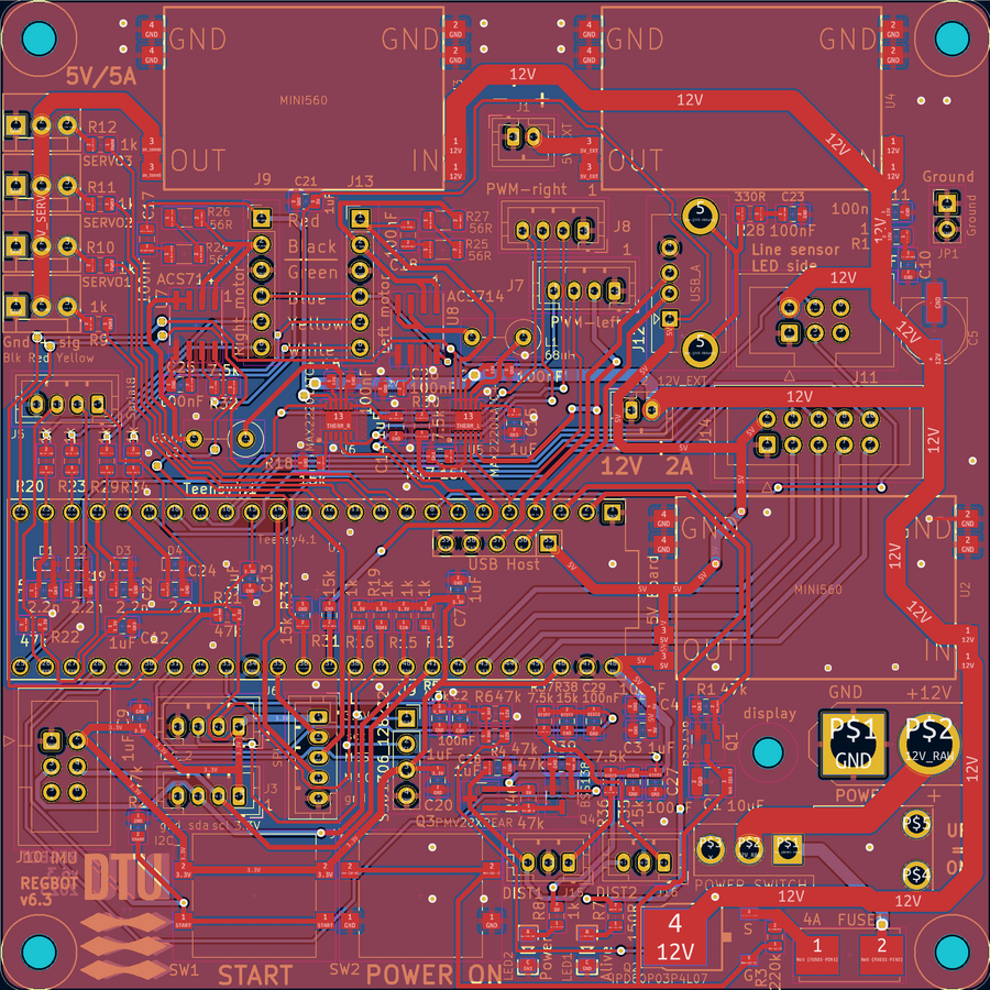
Figure 4. | Figure 4. PCB layout. | ||
[[File:regbot_6.3_PCB_2.png | 900px]] | [[File:regbot_6.3_PCB_2.png | 900px]] | ||
Figure 5. PCB with more trace details. | Figure 5. PCB with more trace details. | ||


