Regbot hardware board: Difference between revisions
No edit summary |
No edit summary |
||
| Line 5: | Line 5: | ||
=== Motor type === | === Motor type === | ||
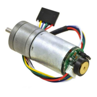
[[file:regbot-motor-jga25-370.png | | [[file:regbot-motor-jga25-370.png | 200px]] | ||
The Regbot/Basebot motor is of the type JGA25-370. | The Regbot/Basebot motor is of the type JGA25-370. | ||
Revision as of 14:36, 17 October 2024
Back to Regbot
Back to Basebot
Motor type
The Regbot/Basebot motor is of the type JGA25-370.
O-LED display
The display shows the robot's status. The top line will show the robot type (in this case Robobot), but can be replaced by user software. The center line is the robot's number and name. The bottom line shows time in seconds (to see that it is alive), the battery voltage, the hardware type (the PCB version, in this case 8), and a device status string.
The device string, here "MMuIdGA", shows some status. Capital letters mean inactive.
- MM: Motor left and right. Lowercase means the motor controller is active.
- U: Is the USB connection active?
- I: Is the IMU (accelerometer and gyro) active?
- D: Is the distance sensor (IR sensor) active (powered)?
- G: Is the gamepad active (Green gamepad using the USB-host connector) and in manual control mode?
- A: Is the magnetic encoder connected (AS5147 on SPI-bus)?
Some of these letters may be missing if they are irrelevant to the robot and the software removed.
Circuit diagram
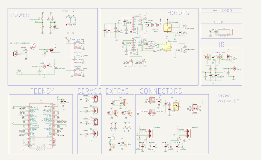
Figure 1. The Regbot circuit - version 6.3. Click (twice) to zoom.
PCB - 3D view
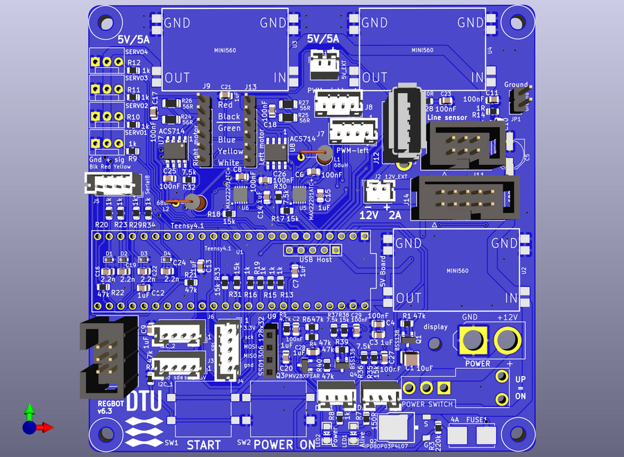
Figure 2. 3D view from KiCad (version 6.3 PCB).
PCB
Figure 4. PCB layout.
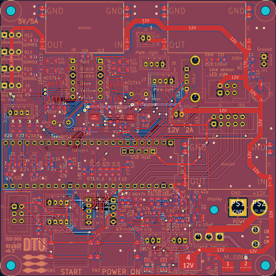
Figure 5. PCB with more trace details (Version 6.3 PCB).


