Robobot architecture: Difference between revisions
No edit summary |
|||
| Line 18: | Line 18: | ||
The desired wheel velocity for each wheel is generated in the mixer from a desired linear and rotational velocity. | The desired wheel velocity for each wheel is generated in the mixer from a desired linear and rotational velocity. | ||
=== | === Blocks === | ||
More [[robobot level 1]] details of the individual blocks. | More [[robobot level 1]] details of the individual blocks. | ||
Revision as of 11:14, 22 October 2023
Back to Robobot B
NASREM
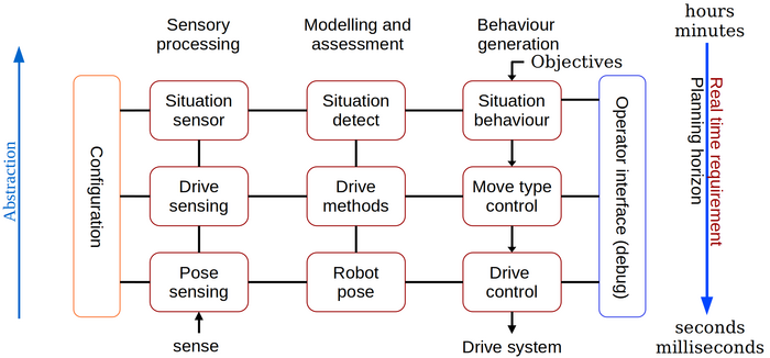
The software architecture is based on the old NASREM architecture, and this is the structure for the description on this page.
The National Aeronautics and Space Administration (NASA) and the US National Institute of Standards and Technology (NIST) have developed a Standard Reference Model Telerobot Control System Architecture called NASREM. Albus, J. S. (1992), A reference model architecture for intelligent systems design.
Figure 1. The NASREM model divides the control software into a two-dimensional structure. The columns are software function: Sensor data processing, modelling and behaviour control.
Level 1; drive control
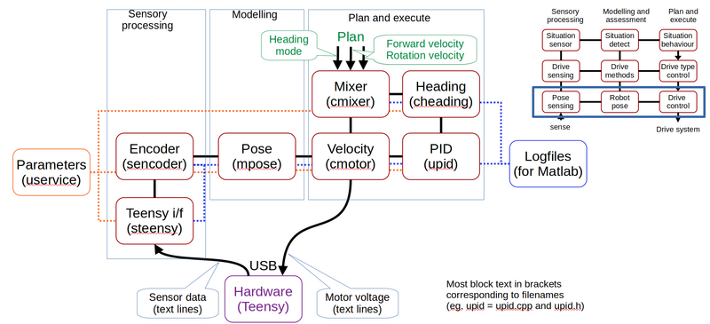
Figure 2. The lowest level in the control software. The encoder ticks are received from the hardware (from the Teensy microprocessor) in the sensor interface. The encoder values are then modeled into an odometry pose. The pose is used to control the wheel velocity using a PID controller. The desired wheel velocity for each wheel is generated in the mixer from a desired linear and rotational velocity.
Blocks
More robobot level 1 details of the individual blocks.
Level 2; drive select
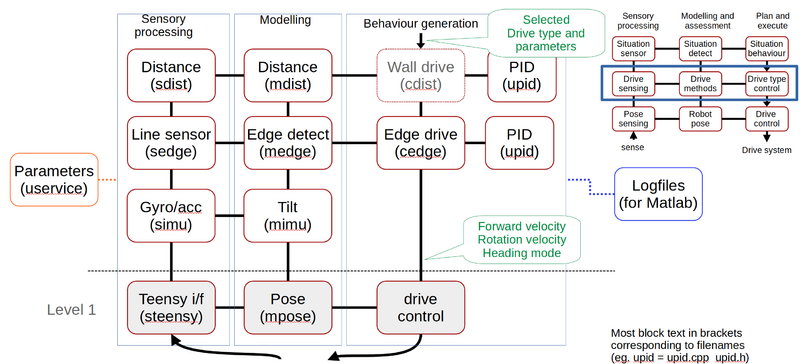
Figure 3. At level 2 further sensor data is received, modeled, and used as optional control sources.
Detailed description level 2
More robobot level 2 details of the individual blocks.


