Scorpi modules
Back to Scorpi
Overview of hardware interface
This overview is focused on the hardware and hardware interface modules used as the basis for controlling the Scorpi system.
The described software module relates to the source code file where the module is implemented.
Processor boards
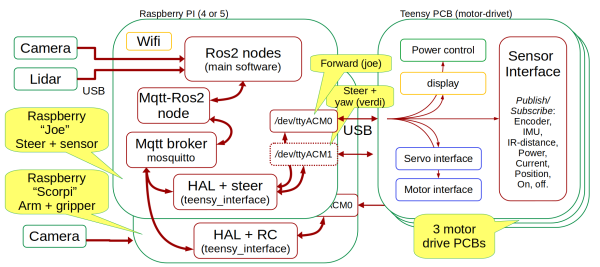
The Scorpi system has two Raspberry Pi processors (version 4 and 5) and three hardware interface boards (Teensy motor drive boards).
The main functionality for autonomous operation is handled in the ROS2 nodes.
Camera and Lidar interface directly to ROS2 using ROS drivers.
All other sensors and actuators are interfaced through a MQTT-ROS2 node. There is one MQTT broker only.
The hardware abstraction layer (HAL) in a Teensy_interface application generates MQTT messages from the hardware. Both Raspberry Pi processors run a teensy_interface, sending data to the same MQTT message broker.
The messages sent to the MQTT broker are (mostly) text strings. The last word in the MQTT topic is the message keyword. The message payload is coded as text, mostly numerical, and always separated by a space character.
The teensy_interface uses USB to talk to one or two processor boards with a Teensy 4.1 processor. The Teensy software is called motor_drive.
Each board includes four motor drivers, an interface to three angle encoders, two MPUs, and other items.
The board also delivers power to the Raspberry Pi and handles the power on and off.
A subscription service in the motor_driver controls the data rate and selection. The teensy_interface manages the subscriptions as specified in a configuration file called "robot.ini."
Drive control
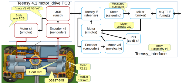
The forward drive uses four motors, two on each wheel. Two motors give more power and reduce backlash by driving each motor with a different offset voltage.
All motors have rotation encoders and are velocity-controlled from the teensy_interface. When Scorpi is turning (controlled by the front wheels), the velocity of the driving wheels is adjusted to match the curvature.
The following status is available through MQTT:
- Motor velocity: Topic "scorpi/drive/T1/mvel" has a payload "m1 m2 m3 m4", a text string with the estimated velocity in rad/sec of the motor before the gear.
- Motor voltage: Topic "scorpi/drive/T1/motv" has a payload "v1 v2 v3 v4", a text string with the voltage applied to the motors (in Volts).
The MQTT topic levels are:
- The system level, here "scorpi".
- The function division, here "drive", could also be "crane". The "drive" functions control the forward drive motors, the steering and the crane yaw. The "crane" function controls the gripper and the x-y movement (arm and stick).
- The board level, here "T1", could also be "T2". Each board control up to four motors.
Steering
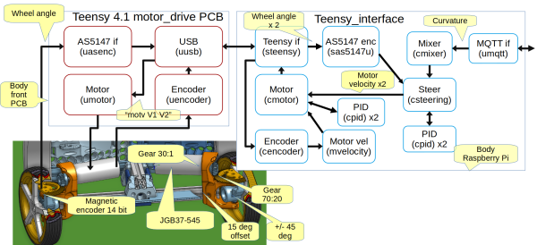
Each steering wheel has a motor-driven steering angle. The motor has a rotation encoder used in a motor velocity control loop (cmotor).
The motor has an internal gear (18:1) and a crown gear (70:20) to the steering angle. An absolute angle measurement, a 14-bit magnetic encoder AS5147, measures the actual angle. The wheel angle is used in a steering control loop.
Each steering wheel can turn +/—45 degrees relative to the steering motor, which is angled by 15 degrees relative to the robot body. This gives the steering wheel an angle from 60 to -30 degrees (for the left wheel). These angles are to mechanical stops and are limited to a few degrees less in software. This gives a turning radius of about 0.6m, assuming an axle distance of 0.4m and a wheel separation of 0.35m.
The MQTT messages related to steering are:
- Steering: The topic "scorpi/drive/steer" has payload "a1 a2 c", where a1 and a2 are the steering wheel angle, in radians, for the left and right wheel, and c is the resulting turn curvature (c = 1/(turn radius)).


