Scorpi modules
Back to Scorpi
Overview of hardware interface
This overview is focused on the hardware and hardware interface modules used as the basis for controlling the Scorpi system.
The described software module relates to the source code file where the module is implemented.
Processor boards
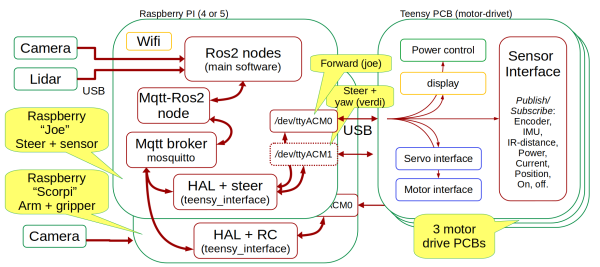
The Scorpi system has two Raspberry Pi processors (version 4 and 5) and three hardware interface boards (Teensy motor drive boards).
The main functionality for autonomous operation is handled in the ROS2 nodes.
Camera and Lidar interface directly to ROS2 using ROS drivers.
All other sensors and actuators are interfaced through a MQTT-ROS2 node. There is one MQTT broker only.
The hardware abstraction layer (HAL) in a Teensy_interface application generates MQTT messages from the hardware. The Raspberry Pi processors run a teensy_interface, exchanging data to the same MQTT message broker.
The messages published to the MQTT broker are all text strings. The last word in the MQTT topic is the message keyword. The message payload is coded as mostly numerical text and is always separated by a space character.
The teensy_interface uses USB to talk to one or two processor boards with a Teensy 4.1 processor. The Teensy software is called motor_drive.
Each board includes four motor drivers, an interface to three angle encoders, two MPUs, and other items.
The board also delivers power to the Raspberry Pi and handles the power on and off.
A subscription service in the motor_driver controls the data rate and selection. The teensy_interface manages the subscriptions as specified in a configuration file called "robot.ini."
Drive control
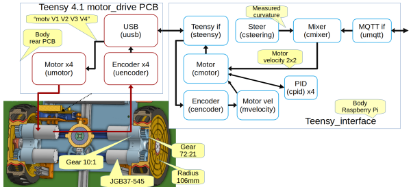
The Teensy board should be at /dev/ttyACM0, called "91 Joe", and be placed in the back under the crane. The board function is 1 : FUNC_REAR_DRIVE.
The connected Raspberry Pi have the hostname "Joe".
The forward drive uses four motors, two on each wheel. Two motors give more power and reduce backlash by driving each motor with a different offset voltage.
All motors have rotation encoders and are velocity-controlled from the teensy_interface. When Scorpi is turning (controlled by the front wheels), the velocity of the driving wheels is adjusted to match the curvature.
The following status is available through MQTT:
- Motor velocity: Topic "scorpi/drive/T1/mvel" has a payload "m1 m2 m3 m4", a text string with the estimated velocity in rad/sec of the motor before the gear.
- Motor voltage: Topic "scorpi/drive/T1/motv" has a payload "v1 v2 v3 v4", a text string with the voltage applied to the motors (in Volts).
- Motor voltage: Topic "scorpi/drive/T1/motc" has a payload "a1 a2 a3 a4", a text string with the current measured for motors (in Amps) and is always positive. The motor voltage is handled in the teensy_interface by a "scurrent" module (not shown).
Robot.ini
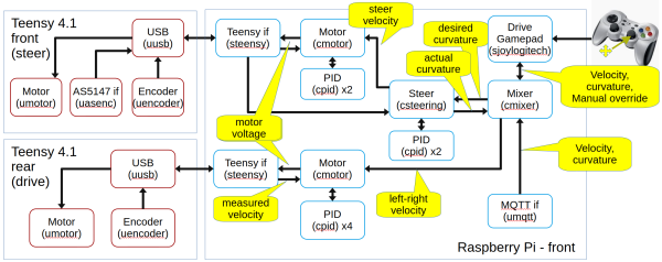
The mixer cmixer.cpp takes desired velocity and turn curvature. The turn curvature is transferred to steering control. The the current steering angle is provided from steering control and is mixed with desired velocity to get desired wheel velocity left and right.
[mixer]
log = true
print = false
driveleft  = 0 0 1          Drive motors left connected to teensy 0, motor 0 and 1
driveright = 0 2 3          Drive motors right connected to teensy 0, motor 2 and 3
turnleft   = 1 2 -1         Turn motors left  front wheel: connected to teensy 1, motor 2
turnright  = 1 3 -1         Turn motors right front wheel: connected to teensy 1, motor 3
wheelbase  = 0.34           (m) distance between rear driving wheels.
motor_gear = 10             Gear in drive motor 10:1
drive_gear = 3.42857142857  Gear in drive wheel 21:72
wheel_radius = 0.103        (m)
The motor encoders are used to get measured left and right steering velocity.
[encoder0]
rate_pos_ms = 20
rate_vel_ms = 8
log = true
print = false
encoder_reversed = true
The velocity for Scorpi is estimated by Teensy but maintained and logged by velocity.cpp.
[velocity]
enctickperrev = 68    (not used)
useteensyvel = true   (Teensy is better at estimating velocity)
log = true
print = false
The motor control settings are part of the cmotor.cpp code and is using these parameters shown below.
All motors should use the same control parameters, but there should be a different between the two motors for each wheel, about 0.5V, to limit the backlash effect.
[motor_teensy_0]
m1kp = 0.1          (v/rad) motor voltage per rad/s error.
m1lead = 0 1.0      Lead zero tau (sec), alpha (time factor for lead pole relative to zero tau)
m1taui = 0.0        Integrator time constant (sec)
m1feedforward = 0   Feed forward from reference to motor voltage
m1maxmotv = 4.0     (v) Limit the maximum motor voltage (it is 12V motors)
m1voffset = 0.3     (v) offset added to motor voltage
m2kp = 0.1
m2lead = 0 1.0
m2taui = 0.0
m2feedforward = 0
m2maxmotv = 4.0
m2voffset = -0.3
m3kp = 0.1
m3lead = 0 1.0
m3taui = 0.0
m3feedforward = 0
m3maxmotv = 4.0
m3voffset = 0.3
m4kp = 0.1
m4lead = 0 0.3
m4taui = 0.0
m4feedforward = 0
m4maxmotv = 4.0
m4voffset = -0.3
log_voltage = true        For all motors
motv_sample_time = 33     (ms) update rate
motpwm_sample_time = 0    (ms) update rate - 0 means no updates
m1log_pid = true
m2log_pid = true
m3log_pid = true
m4log_pid = true
MQTT
The MQTT topic levels are:
- The system level, here "scorpi".
- The function division, here "drive", could also be "crane". The "drive" functions control the forward drive motors, the steering and the crane yaw. The "crane" function controls the gripper and the x-y movement (boom and arm).
- The board level, here "T1", could also be "T2". Each board control up to four motors. The board level is omitted if not board-related.
- Keyword is the last string and is typically the keyword used in the Teensy board.
Steering
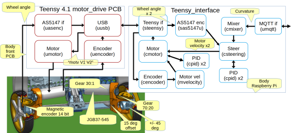
The Teensy board should be /dev/ttyACM1, called "92 Stub", and placed in the front under the bonnet. The board function is 2: FUNC_STEER_YAW.
The connected Raspberry Pi have the hostname "Joe".
Each steering wheel has a motor-driven steering angle. The motor has a rotation encoder. This is used in a motor velocity control loop (cmotor).
The motor has an internal gear (18:1) and a crown gear (70:20) to the steering angle. An absolute angle measurement, a 14-bit magnetic encoder AS5147, measures the actual angle. The wheel angle is used in a steering control loop.
Each steering wheel can turn +/—45 degrees relative to the steering motor and is angled by 15 degrees relative to the robot body. This gives the steering wheel an angle from 60 to -30 degrees (for the left wheel). These angles are to mechanical stops and are limited to a few degrees less in software. This gives a turning radius of about 0.6m, assuming an axle distance of 0.4m and a wheel separation of 0.35m (curvature 1.6 rad/m).
Robot.ini [steer]
The configuration for turning is used by steering.cpp.
[steer]
axledistance = 0.40   (m)
wheelseparationfront = 0.35   (m)
kp = 150.0
lead = 0 0.3
taui = 0.0
ff = 0
maxCurvature = 10.6   (rad/m) radians turned per meter driven
turnteensy = 1  (teensy with AS5147 angle measurement (device 0 and 1))
log = true
print = false
The mixer sets the steering motors:
[mixer]
log = true
print = false
driveleft = 0 0 1    Drive motors left connected to teensy 0, motor 0 and 1
driveright = 0 2 3   Drive motors right connected to teensy 0, motor 2 and 3
turnleft = 1 2 -1    Turn motors left  front wheel: connected to teensy 1, motor 2
turnright = 1 3 -1   Turn motors right front wheel: connected to teensy 1, motor 3
wheelbase = 0.34     (m) distance between rear driving wheels.
MQTT
The MQTT messages related to steering are:
- Steering: The topic "scorpi/drive/steer" has payload "a1 a2 c", where a1 and a2 are the steering wheel angle, in radians, for the left and right wheel, and c is the resulting turn curvature (c = 1/(turn radius)).
Crane control
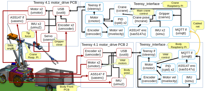
The crane control is split into two Raspberry Pi and two Teensy motor controller boards.
The Teensy board on the arm is /dev/ttyACM0, called "93 scorpi". The board function is 3: FUNC_CRANE.
The Raspberry Pi on the arm is called "Scorpi". The Teensy that controls the yaw (under the hood) is called "92 Stub". The "Stub" Teensy is connected to the "Joe" Raspberry Pi as /dev/ttyACM1 with board function 1: FUNC_STEER_YAW.
The rotating part (x-y and gripper control) is handled by the motor controller and the Raspberry Pi on the arm itself. The yaw motion is handled by the same motor controller as the steering and by the Raspberry Pi embedded in the vehicle.
Gripper
A rubber joint connects the arm (the horizontal part of the crane) and the gripper arm. The load on the gripper changes the angle between the arm and the gripper, which the two MPUs can measure.
A small motor operates the gripper, and a force sensor detects the gripper force.
Crane arm
A magnetic encoder (AS5147) measures the angle between the boom and the arm.
Both actuators (for boom and arm) have encoders for motor velocity estimates.
The boom (the vertical part) actuator is connected as motor 1 (of 4) and is a 150mm stroke Transmotec DLA 12V actuator with 1:10 gearing (23.5 encoder ticks per mm).
The arm (the horizontal part) actuator is connected as motor 2 (of 4) and is a 250mm stroke Transmotec DLA 12V actuator with 1:20 gearing (12.3 encoder ticks per mm).
Yaw
The yaw (swing motion) has two motors (to reduce slag) with encoders for velocity control. A magnetic encoder (AS5147) measures the yaw angle. This encoder is geared 26:74 so that the crane can rotate more than 360 degrees without repeating the same angle from the magnetic encoder (actually almost three rotations, but the wires will curl in the crane base, so don't rotate too much).
Tilt and roll
A third MPU measures the vehicle's tilt and roll. The yaw control and the IMU data are transferred to the crane Raspberry Pi using MQTT.
The tilt and roll, together with the yaw angle and the angle from the two IMUs on the crane, are used to determine the absolute pose of the crane (crane).
Crane control
The crane control module (ccrane) can (if implemented) be ordered using joint angles or end effector position.
Trailer control
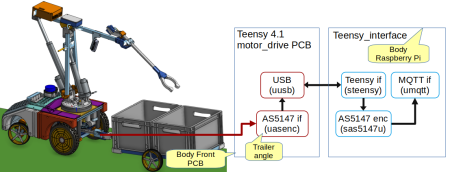
A magnetic encoder (AS5147) can measure the vehicle-trailer joint. This is intended for control when the robot reverses with the trailer.
The encoder is connected to the "91 Joe" Teensy board.
Remote control
The gamepad can take over control (manual control) by pressing "back" and go to autonomous drive by pressing "run".
The gamepad delivers a desired velocity (forward) and a desired curvature. The "RB" button enables faster drive - but be careful.
The mixer uses data from the gamepad when in manual drive. The mixer sends the desired curvature (in radians per driven meter) to the steering controller. The mixer uses actual steering curvature and desired velocity to generate left and right drive wheel velocity.
The steer controller sets the desired steer motor velocity. The steer implements the maximum curvature (set in the robot.ini file) to 1.6 radians per driven meter (turn radius 0.6m).
Robot.ini
Remote control supports (pt) just Logitect F710.
These settings can be configured:
[joy_logitech]
log = true
print = false
device = /dev/input/js0
limit = 1.0 10.0          Maximum value: linear (m/s) and curvature (rad/m),
button_fast = 5          Button to allow full speed (button marked 'RB')
axis_vel = 4             Axis for velocity control (right stick up-down)
axis_turn = 3            Axis for turning (right stick left-right)
slow_factor = 0.3        Normal reduction of control speed, used unless 'button_fast' is pressed
axis_servo = 1           Axis to control servo (not used on drive system) (left stick up-down)
servo = 1
log_all = false
device_type = Logitech Gamepad F710
MQTT
The MQTT is assumed to acquire the desired velocity and curvature, which are used in autonomous mode.
Sensor interface
This section gives more details about sensor modules.
Inertia measurements
The MPU has 3-axis accelerometer and gyro.
The motor_controller can handle two sensors when one of them uses the alternate address on the I2C bus.
An Arduino driver for the MPU is slightly modified and, therefore, included in the source (MPU9250_asukiaaa).
The data is captured at 1k samples per second and filtered depending on the subscribed data rate.
Angular encoder
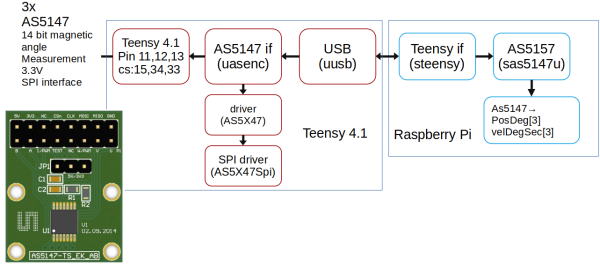
The magnetic encoder is an AS5147, providing a 14-bit absolute angle of the magnet above the sensor. The board is a standard evaluation board from AS (as shown).
The sensor also provides rotation velocity.
The motor driver can interface three AS5147 boards using an SPI interface and three individual chip-select pins.
IR distance sensor
Two Sharp 2Y0A21Y IR distance sensors can be interfaced with the motor controller board.
The output data is analogue but updated at 28.3ms intervals only. The analogue data is sampled at 1k samples per second and filtered with a time constant of 10ms.
Such sensors can be used for collision avoidance but are not implemented pt.
Force sensor
The force sensor uses the same plugs as the distance sensor and must be turned on in the same way, i.e., with the command "iron 1."
The used sensor is RP-C18.3-LT from DFROBOT The force is in the range from 0.2N to 60N.
Two sensors can be interfaced with the motor controller board (using plug "dist1" and "dist2").
The is analogue but averaged over about 10ms.
A set of sensors are implemented in the gripper pull motor. The actual gripper force (between claws) must be scaled with the claw-arm ratio.
Display
Status display
A small OLED display (128x32 pixels) is interfaced with the motor_controller.
It is intended for fast board status, and one line can be controlled from the Raspberry PI using a "disp text" command.
The display update takes a long time and is thus divided into partial updates, each taking less than 1 ms. This data transfer will, at times, delay other sensor updates.
LED band
An LED band can be interfaced with the motor_controller board using the serial port (The TX-wire only).
Each LED can be set with a "led N R G B" command, where N is the LED number and "R G B" is the intensity for each color (0..255).
The LED interface uses DMA and thus does not interfere with the timing.
The LED is supplied from the same 5V as the servo and Raspberry Pi.
Actuator interface
Motor driver
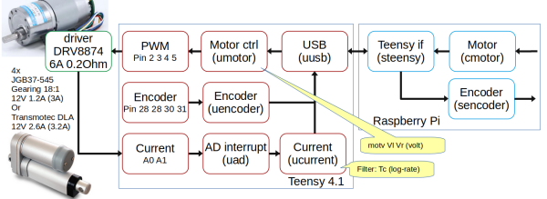
The motor controller has four motor controllers of the type DRV8874. It is capable of driving brushed motors up to 6 amps but is limited to about 4 Amps.
The motor driver is controlled using a single PWM signal, typically 64kHz. At 50% PWM, the motor is stationary; more is forward, and less is reverse for each motor.
The motor controller has a current output. The current is sampled at 1k samples per second; this is insufficient for the 64kHz signal, as there is no filter in this board version.
All the used motors have built-in quadrature encoders. The A and B signals are timed using an interrupt, and the timing can be used to estimate velocity.
Servo
The servo interface provides a positive pulse between 1 and 2ms at a rate of 333Hz. A separate DC-DC converter provides the 5V for the servo.
Power control
Power on
If the battery is off, i.e., there is no light in the battery on button, then turn it on using the button.
This will (in most cases) also turn on the system. The exception is if it was recently turned off. In that case, the power-on microswitch needs to be activated, too.
The motor_controller board holds the power-on switch. A MOSFET controls the power from the battery. When the switch is pressed, the MOSFET turns on.
When the Teensy is booted, pin 35 goes high, keeping the power on.
Power on relay
When power is turned on (by the switch or from firmware), a signal is available to turn on an additional board (the out-on plug).
Shutdown request
The Raspberry Pi must be shut down before power is removed. Therefore, a shutdown must be requested.
Shutdown can be initiated by the "off request" microswitch or the start/off switch on the motor driver board.
The motor driver board reaction may vary.
- On a Robobot
- < 5 seconds, initiate mission start.
- > 5 seconds, initiates a shutdown.
- On Scorpi, any press initiates a shutdown.
A shutdown can also be initiated from MQTT:
topic: robobot/cmt/T0/off (to teensy 0)
message: 40  (number of seconds to allow the Raspberry to shut down)
Shutdown processing
The Teensy sends a "power off" message to the "teensy_interface," which is relayed on the MQTT side. The MQTT message informs all subscribers about the shutdown request.
The "urobot" module in the "teensy_interface" sends an MQTT "shutdown" message. The "shutdown" message is
topic: "robobot/cmd/shutdown"
message: Name of off-requester, e.g. "Teensy"
The "teensy_interface" will then (after 2 seconds) terminate.
The "off_by_mqtt" process will receive the MQTT shutdown message. Five seconds later it will issue the BASH command "shutdown now." The "off_by_mqtt" runs with root privileges.
This will terminate any additional processes and make a nice shutdown.
After 40 seconds, the Teensy boards will cut their power.
The battery load should now be close to zero (only the battery BMS and the on-switch LED should be left active.
