Robobot architecture
Back to Robobot B
NASREM
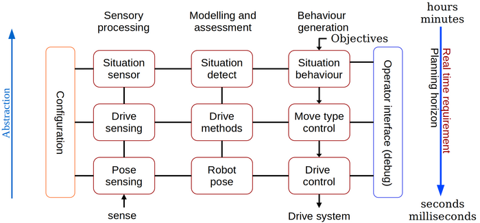
The software architecture is based on the old NASREM architecture, and this is the structure for the description on this page.
The National Aeronautics and Space Administration (NASA) and the US National Institute of Standards and Technology (NIST) have developed a Standard Reference Model Telerobot Control System Architecture called NASREM. Albus, J. S. (1992), A reference model architecture for intelligent systems design.
Figure 1. The NASREM model divides the control software into a two-dimensional structure. The columns are software function: Sensor data processing, modelling and behaviour control.
Level 1
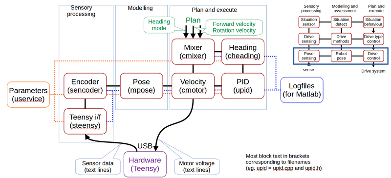
Figure 2. The lowest level in the control software. The encoder ticks are received form the hardware (from the Teensy microprocessor) in the sensor interface. The encoder values are then modeled into an odometry pose. The pose is used to control the wheel velocity using a PID controller. The desired wheel velocity for each wheel is generated in the mixer from a desired linear and rotational velocity.
Teensy i/f
This is the Teensy interface controlling the USB interface to the Teensy.
Commands to the Teensy can be sent in two ways, trusted or best effort. The trusted commands await a confirmation from the Teensy, if this is not received within 30ms, then it is resent - up to 3 times. If still not confirmed, then the message is dropped (most likely the connection is dead or two applications are listening to the same USB device. The 'best effort' tye is sent once only, this is the fastest communication - like motor voltage in a control loop. If one message is lost, then a similar value will be sent at the next sample time.
Both types are further secured by a simple CRC check.
All received messages are sent to the service module for decoding. All outgoing messages use the send method in this module.
All communication on the interface can be logged.
The module is coded in the steensy.h/steensy.cpp files.
The messages look like this - timestamped by the logging function
% teensy communication to/from Teensy
% 1 	Time (sec) from system
% 2 	(Tx) Send to Teensy
%   	(Rx) Received from Teensy
%   	(Qu N) Put in queue to Teensy, now queue size N
% 3 	Message string queued, send or received
1687200276.5853 Tx ;75!setid robobot
1687200276.5853 Rx ;04hbt 47.9792 128 1581 4.64 0 7 74.1
1687200276.5866 Rx ;57# got new name (get with 'id')
1687200276.5867 Rx ;65confirm !setid robobot
1687200276.5869 Tx ;80!setidx 2
1687200276.5880 Rx ;70confirm !setidx 2
1687200276.5881 Tx ;47!idi
1687200276.5892 Rx ;37confirm !idi
1687200276.5893 Rx ;57dname robobot Sofia
1687200276.7838 Qu 1 ;01!sub enc 7
1687200276.7839 Qu 2 ;04!sub hbt 500
1687200276.7842 Qu 3 ;34!sub gyro0 12
1687200276.7842 Qu 4 ;78!sub acc0 12
1687200276.7842 Qu 5 ;37!gyrocal 0 0 0
1687200276.7842 Tx ;01!sub enc 7
1687200276.7853 Qu 6 ;81!sub svo 50
1687200276.7853 Rx ;90confirm !sub enc 7
The CRC is coded as two numeric characters that are the sum of all non-control characters in the message. The sum is reduced to two digits by a modulus 99 and 1 is added to avoid '00'. The two numbers are preceded by a semicolon ';'. Messages that need a confirmation are queued and an '!' are added after the CRC code. The '!' is included in the CRC calculation.
Messages are coded as a character line, coded in 7-bit ASCII, i.e. no danish characters.
Level 2
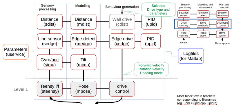
Figure 3. At level 2 further sensor data is received, modelled and used as optional control sources.


