Robobot circuits
Back to Robobot_B
Digital IO
Circuit diagram
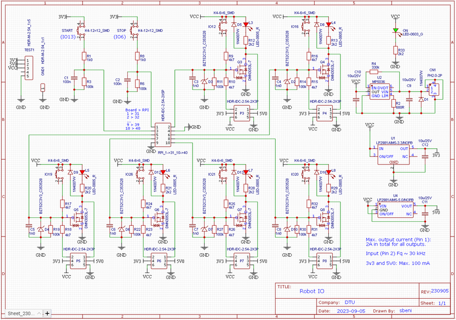
Figure 1. The circuit diagram should ensure that each IO pin can function as both input and output. If input, then the pin has active pull down, i.e. for input to change, it must be pulled high, to at least 3.3V, but 5 or 12V will work too. If output, then a transistor is active when output is high, and can draw at least 1A from the 12V supply. The 5V and 3.3V can supply no more than 100mA.
PCB
Figure 2. The PCB layout for the digital IO circuit.
Robobot
Circuit diagram
Figure 3. The Robobot circuit for version 8.5 (circuit is the same as version 8.4).
PCB
Figure 4. PCB with more trace details.
PCB view
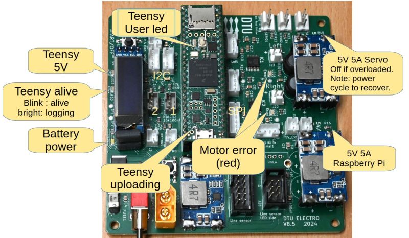
Figure 5. Populated PCB with Teensy 4.1 and O-LED display.
PCB plugs and devices
Figure 6. Connectors. The unused connectors are 2 I2C plugs (I2C and I2C1), an SPI plug (with a driver for AS5147), and a power ON-OUT that can be used to power other similar boards (connect to on-in).
PCB LEDs
Line sensor
Circuit
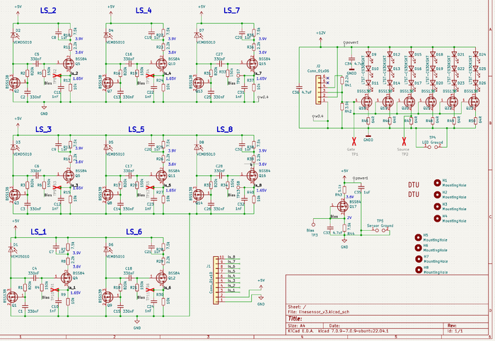
Figure 7. Circuit diagram for the line sensor. 8 sensors with a change amplifier and analogue output. The 18 LEDs provide the blinking light at the sample rate (on Regbot 1kHz).
Function
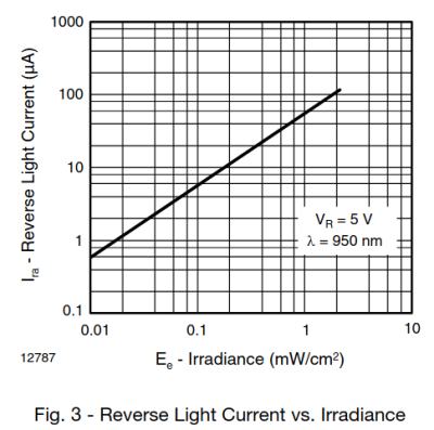
The sensor has a linear characteristic over almost 3 decades of background illumination. If additional illumination is about 0.025 mW/cm^2, the sensor current will increase about 1 uA. This requires a constant voltage across the sensor.
For sensor 1 (shown), Q1 ensures a constant voltage across the sensor D1. The illumination LEDs are turned on and off at half-sample intervals, this gives a current variation in the sensor. Q1 has a very high impedance, due to the gate capacitor, so the current variation through especially R4 (150kOhm) gives a voltage to the gate of Q4. This is amplified with a factor 4.5 to the output at ls_1.
PCB
Figure 8. The PCB in 3D view. The distance from the first to the last sensor is 12cm.
Figure 9. PCB layout.
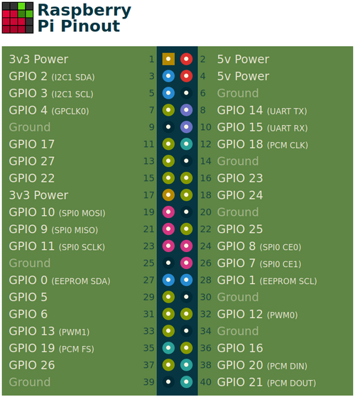
Raspberry PI pinout
Figure 9. GPIO pin numbers, the bottom 10 pins are used for the IO-board. Pin1 on the cable match Pi pin 31 (GPIO6).
