Robobot architecture: Difference between revisions
| (80 intermediate revisions by the same user not shown) | |||
| Line 1: | Line 1: | ||
Back to [[Robobot | Back to [[Robobot_B | Robobot]] | ||
== | == Display and LED-band == | ||
=== O-LED display === | |||
[[file:o-led-display-ann.jpg | 500 px]] | |||
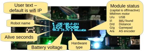
The primary function of this display is the battery voltage. The AS encoder is not used by Robobot. | |||
=== LED-band === | |||
[[file:led-band-annotated.jpg | 750px]] | |||
The Teensy maintains the LED band. Most LEDs show sensor values. The last 3 LEDs can be set by commands to the Teensy. | |||
== Hardware block overview == | |||
[[File:robobot-in-blocks-2024.png | 600px]] | |||
Figure 1. The main hardware building blocks. | |||
== Software building blocks == | |||
[[File:robobot-function-blocks.png | 600px]] | |||
Figure 2. The main software building blocks. | |||
The blocks marked with a blue dot are available in the repository as source code. | |||
The | ==== Mission app==== | ||
The mission app block is the robot's top-level controller. | |||
It can subscribe to data streams from the Teensy interface and command the robot to perform actions (like forward and turn velocity). | |||
It attaches to the camera video stream and connects to the IO board (e.g. the start and stop buttons. | |||
The mission app is in svn/robobot/mqtt_python; its main file is ''mqtt-client.py.'' | |||
== | ==== Teensy interface ==== | ||
The Teensy interface connects the Teensy USB interface and the MQTT protocol. | |||
The Teensy interface further has closed-loop control for forward velocity and implements turn-rate commands. | |||
The interface decodes many essential data types and allows these data streams to be logged. | |||
The logged files are text-based and intended for Matlab for analysis and debugging. | |||
See more details in [[Robobot teensy interface]]. | |||
==== Mosquitto MQTT server ==== | |||
This Mosquitto server is an open-source MQTT protocol server - see https://mosquitto.org/. | |||
This server is running as a service. | |||
==== Camera streamer==== | |||
The camera streamer is a small Python app that takes data from the camera and streams the video to socket port 7123. | |||
This means that the stream is also available on Wi-Fi. | |||
See [[Robobot webcam server]] for more details | |||
==== IP-disp ==== | |||
IP_disp is a silent app that is started at reboot (by ''on_reboot.bash'') and has two tasks: | |||
* Detect the IP net address of the Raspberry and send it to the small display on the Teensy board (inactive if the Teensy_interface is running.) | |||
* Detect if the "start" button is pressed, and start the mission app. | |||
* Detect if the "start" button is pressed for more than 5 seconds to shut down the robot. | |||
==== Digital IO ==== | |||
This is the board on top of the Robobot. It provides digital IO and a power supply for external devices. | |||
The IO is connected to the Raspberry PI pins GPIO06 (stop), 13 (start), 16, 19, 20, 21, and 26. | |||
See details in [[Robobot circuits]]. | |||
==== Teensy PCB ==== | |||
The Teensy board is a baseboard used in the more straightforward 'Regbot' robot. | |||
This board has most of the hardware interfaces and offers all sensor data to be streamed in a publish-subscribe protocol. | |||
All communication is based on clear text lines. | |||
The firmware is in ''svn/robobot/teensy_firmware_8'', compiled with ''./compile'' and uploaded to the Teensy by ''./upload''. NB! An upload will cut the battery power, so press the ''power'' switch during upload. | |||
See details in [[Robobot circuits]]. | |||
== Start buttons (and external power) == | |||
[[file:start-buttons.png | 600px]] | |||
The two start buttons are quite different. | |||
* The Arduino mission start will start the mission code in the Teensy. | |||
* The IO Start button is read by ''ip_disp'' and starts the Python script mentioned in ''mission_start.bash''. | |||
Both buttons can shut down the robot when pressed for 5 seconds. | |||
The digital-io (except the start button) can only be used from the Python script. | |||
=== External power === | |||
On the digital-io board, there are power pins available for 3V, 5V, and 12V. 12V is the battery voltage, which can vary from 10 to 16V. | |||
Latest revision as of 16:30, 1 February 2026
Back to Robobot
Display and LED-band
O-LED display
The primary function of this display is the battery voltage. The AS encoder is not used by Robobot.
LED-band
The Teensy maintains the LED band. Most LEDs show sensor values. The last 3 LEDs can be set by commands to the Teensy.
Hardware block overview
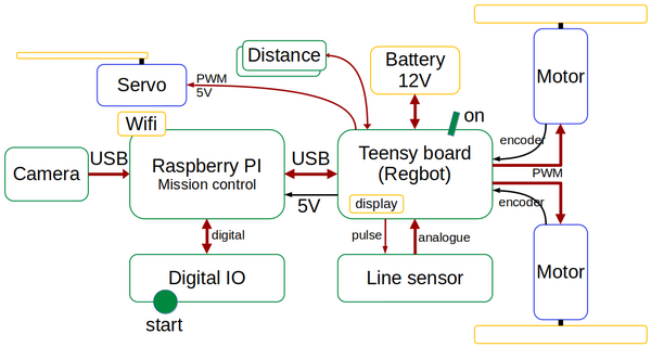
Figure 1. The main hardware building blocks.
Software building blocks
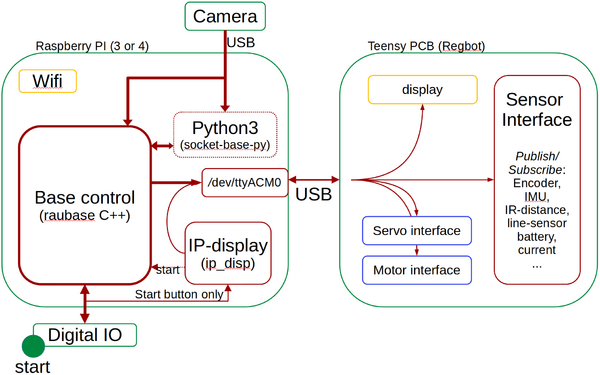
Figure 2. The main software building blocks.
The blocks marked with a blue dot are available in the repository as source code.
Mission app
The mission app block is the robot's top-level controller.
It can subscribe to data streams from the Teensy interface and command the robot to perform actions (like forward and turn velocity). It attaches to the camera video stream and connects to the IO board (e.g. the start and stop buttons.
The mission app is in svn/robobot/mqtt_python; its main file is mqtt-client.py.
Teensy interface
The Teensy interface connects the Teensy USB interface and the MQTT protocol.
The Teensy interface further has closed-loop control for forward velocity and implements turn-rate commands.
The interface decodes many essential data types and allows these data streams to be logged. The logged files are text-based and intended for Matlab for analysis and debugging. See more details in Robobot teensy interface.
Mosquitto MQTT server
This Mosquitto server is an open-source MQTT protocol server - see https://mosquitto.org/. This server is running as a service.
Camera streamer
The camera streamer is a small Python app that takes data from the camera and streams the video to socket port 7123. This means that the stream is also available on Wi-Fi. See Robobot webcam server for more details
IP-disp
IP_disp is a silent app that is started at reboot (by on_reboot.bash) and has two tasks:
- Detect the IP net address of the Raspberry and send it to the small display on the Teensy board (inactive if the Teensy_interface is running.)
- Detect if the "start" button is pressed, and start the mission app.
- Detect if the "start" button is pressed for more than 5 seconds to shut down the robot.
Digital IO
This is the board on top of the Robobot. It provides digital IO and a power supply for external devices.
The IO is connected to the Raspberry PI pins GPIO06 (stop), 13 (start), 16, 19, 20, 21, and 26. See details in Robobot circuits.
Teensy PCB
The Teensy board is a baseboard used in the more straightforward 'Regbot' robot. This board has most of the hardware interfaces and offers all sensor data to be streamed in a publish-subscribe protocol. All communication is based on clear text lines.
The firmware is in svn/robobot/teensy_firmware_8, compiled with ./compile and uploaded to the Teensy by ./upload. NB! An upload will cut the battery power, so press the power switch during upload. See details in Robobot circuits.
Start buttons (and external power)
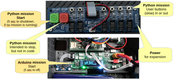
The two start buttons are quite different.
- The Arduino mission start will start the mission code in the Teensy.
- The IO Start button is read by ip_disp and starts the Python script mentioned in mission_start.bash.
Both buttons can shut down the robot when pressed for 5 seconds.
The digital-io (except the start button) can only be used from the Python script.
External power
On the digital-io board, there are power pins available for 3V, 5V, and 12V. 12V is the battery voltage, which can vary from 10 to 16V.


