Robobot
This page is for ROBOBOT, an extension of REGBOT with a raspberry pi and three wheels.
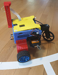
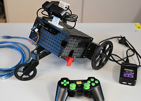
Figure 1. Robobot, The robot is a 3D-printed box with wheels and some electronics. The third, fourth and fifth generations are shown here. The 3D printed parts can be found here https://cad.onshape.com/documents/fef8699fcafb8aea780c8981/w/ce38e7fdd6cf8533b65e2c3c/e/4792e876b254f8e35059f863
Overview
hardware
ROBOBOT is based on a navigation box with a line sensor (Edge sensor), an IR distance sensor and possibly some servos, all controlled by a microprocessor. For more intelligent behaviour and more sensors, there is a Raspberry Pi in the box too,
The motors are JGB37-545 with an encoder and a 1:10 gearing (up to about 400RPM (or ~6 RPS (rotations per second) on the output axle).
There is a video introduction and demo here https://www.youtube.com/watch?v=6dNr_F0dsHw
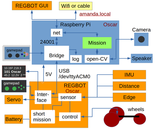
Figure 2. ROBOBOT is an extension of the simpler robot REGBOT. The REGBOT part controls the wheels, interfaces to sensors like an IMU (6 axis accelerometer and gyro), IR distance sensors (2), and a line edge detector. REGBOT further controls up to 3 servos and controls the battery supply. ROBOBOT is further equipped with a Raspberry Pi to allow more complicated missions. On the Raspberry Pi runs an interface process called robobot_bridge, this interfaces to a small 3-5-line display, to a game-pad and is the main interface to the REGBOT. The mission process collects data from the bridge and the REGBOT and supplies small mission code snippets to be executed by the REGBOT part. The mission process may use the camera and the Open-CV library functions. The speaker allows debugging messages or other sound effects.
The ROBOBOT functions are available on the net at port number 24001. The existing user interface for REGBOT can access REGBOT functions from this port.
The gamepad can take control of the robot if the mission fails and can be used to initiate missions or other functions using the gamepad buttons and axis.
Software description
Bridge software
The bridge - called robobot_bridge - runs on the Raspberry Pi and is started when the Raspberry Pi starts.
Robobot_bridge overview
The autostart feature is implemented in the script 'start_bridge.sh' in the home directory of the user 'local'. The is executed after a reboot.
The script can be amended with other commands that should be started after a reboot.
Mission software
The mission application is the primary user control for the robot.
Robobot mission application overview.
The Mission application is started manually from an ssh console or added to the reboot script 'start_bridge.sh'.
Setup issues
Installation instructions
Raspberry and ROS (not finished)
Robobot camera camera setup
Access from Windows minimal setup
Regbot GUI python setup and GUI install
Software update
Update of the maintained software is on the SVN (subversion) repository.
SSH to the robot and go to these directories and do an update
cd
svn up svn/fejemis/ROS/catkin_ws/src/bridge
svn up svn/robobot
svn up svn/regbot
old instructions
Not valid anymore?
This section contains instructions for setting up a clean Raspberry Pi very manually.
Install on raspberry on a clean SD-card - raspi-config.
Setup user local adding a new user.
Linux tools - packages to install.
Network setup Wifi and time
Raspberry Camera API - to use camera from C++ (installed as default)
Sound installation on Raspberry
Robobot on Raspberry PI specifics for ROBOBOT.
Acces from (Windows)
Access from PC (Linux or Windows).
Other windows tools - run graphics from Windows
old stuff
Instructions for getting started - primarily network, Linux intro and wifi setup.
REGBOT setup
A number of parameters in the REGBOT part of the robot need setting.
Some suggestions are provided here using the REGBOT GUI (available on the raspberry in the 'regbotgui' directory, and in a Windows version):
Hardware
The Robobot frame is 3D printed, the design is in onshape - see this link https://cad.onshape.com/documents/fef8699fcafb8aea780c8981/w/ce38e7fdd6cf8533b65e2c3c/e/4792e876b254f8e35059f863 , in the list of parts to the left it is possible to export (right-click) as STL files, that you can slice for your 3D printer.
The REGBOT part of the hardware is described on the Regbot_version_4 page, e.g. schematics and connector pinout.
Connection of the line display to the Raspberry pi is here Robobot Hardware.
The navigation box opened. The main part is a Raspberry pi and the REGBOT low-level control board with a Teensy 3.5.
Navigation box assembly may look a bit complex, but look here for more details.
On this page is a short assembly instruction for the navigation box.
Status
Some status for individual ROBOBOT robots may be available here. ROBOBOT status


